Copyright © AMETEK Page 2–1
2. Product Description
2
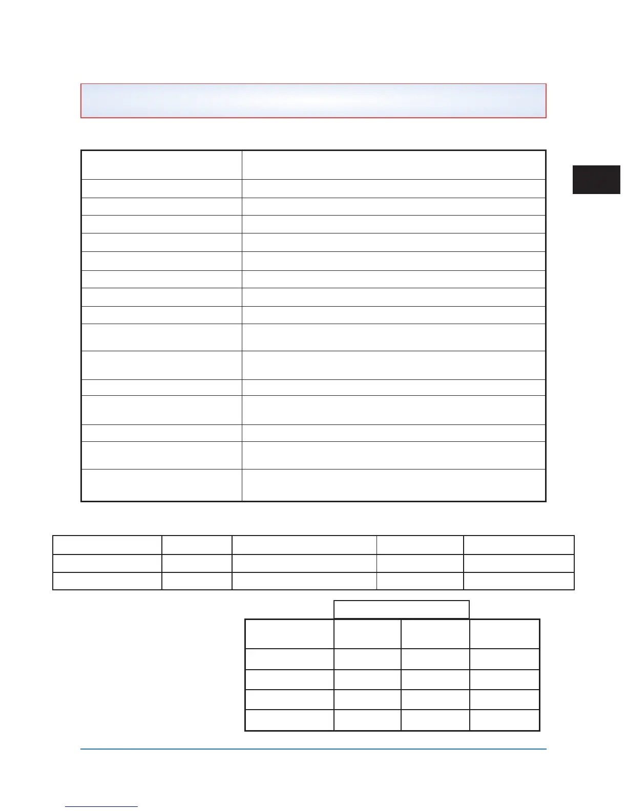
Table 2–1. Basic Transmit / Receive Specifications
Basic Industry Specification Meets or Exceeds requirements of C93.5, ANSI Requirements
for Single Function Power-Line Carrier TX/RX Equipment
Frequency Range 30–535 kHz
TX / RX Frequency Resolution 10 Hz Increments
Frequency Stability ±5 Hz
TX / RX Connections 2-Wire or 4-Wire
TX RF Output Impedance 50 Ω, 75 Ω Nominal Unbalanced
TX RF Output Power 10W Max (20W w/optional redundant amp) 0.3W Min
TX Harmonic & Spurious Output 55 dB Below TX Freq. at Rated Full Power
TX Output Variation ±1 dB Over Temp / Volt Range
TX Reflected Power Monitor ±10 %
Accuracy with Interference
Modulation Type ON/OFF (Amplitude Modulation) or
FSK (Frequency Shift Keyed), Field Programmable
FSK Frequency Shifts Programmable ±100, ±250 or ±500 Hz (See 4-Freq. Table Below)
Minimum In-Band SNR for Good 13 dB for FSK, 20 dB for ON/OFF
Channel Operation
4-Wire Receiver Input Impedance > 4 kΩ
Receiver Sensitivity (Min to Max) 28 mV (Min. with 15 dB Margin) to 70 V (Max),
–20 dBm to +50 dBm @ 50 Ω / 75 Ω
Hot Swappable Power Supply & Power Amp Only
Table 2–2. IRIG-B Load Specificatons
Table 2–3. Frequency
Specifications for 4-Frequency
Special Logic
TX Keyed 600 Hz BW 1,200 Hz BW Frequency
State +/- 250 Shift +/- 500 Shift Designation
Non-keyed +83 Hz +166 Hz F3
Command A +249 Hz +498 Hz F4
Command B –83 Hz –166 Hz F2
Command A & B –249 Hz –498 Hz F1
RX Bandwidth / Shift
2.1 Specifications
Type Connector Load Compatability Signal
Modulated J13 2.5 k Ω Min. (3.5 k Ω Typical) IRIG-B123 Mod. 1 kHz Sine Wave
TTL (Unmodulated) J14 3.8 mA Typical at 5 Vdc IRIG-B003 0–5 V Pulse Train
 Loading...