Page 3–14
UPLC-II™ System Manual
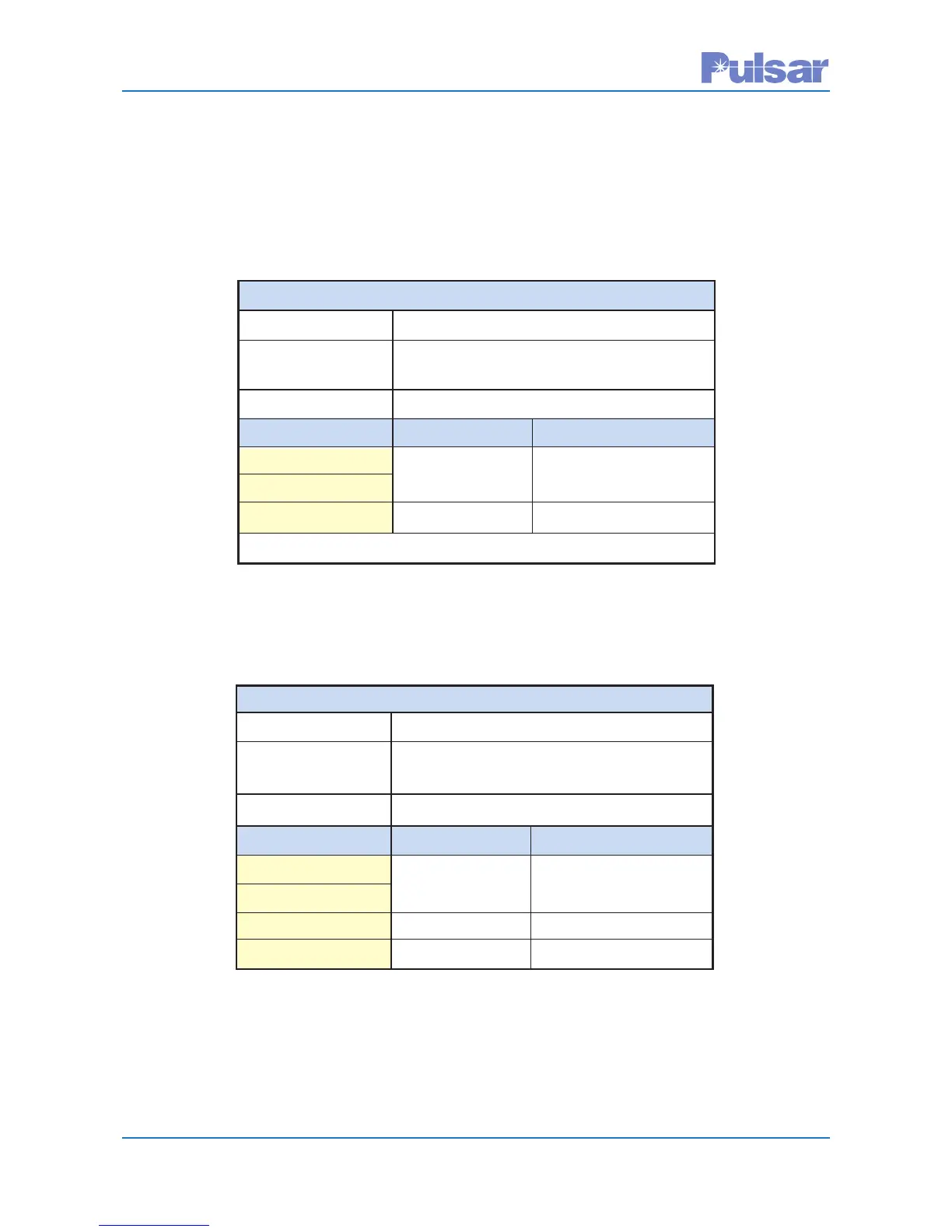
Table 3–2.
Hardware Fixed Alarm (from Power Supply Board)
All Modes
PS Hardware Failure Alarm for All UPLC-II™ Units
Alarm Reason: One of the PS outputs is too low in voltage
Alarm Name: Power Supply Alarm Output
(Available Outputs) (TB1-5 & 6)**
De-Energized State
Contact Type: N.O. Contact N.C. Contact
UPLC-II™ Condition
PS Good Closed Open
PS Bad Open Closed
**For the Redundant Power Supply, use TB2-5 & 6
Table 3–3.
Software Programmable Alarms/(Outputs from I/O Board)
ON/OFF Mode
Hardware Failure Alarm for All UPLC-II™ Units
Alarm Reason: Hardware health of at least one card is bad
Alarm Name: General Alarm Output
(Available Outputs) (LL08 – LL10)
De-Energized State
Contact Type: N.O. Contact N.C. Contact
UPLC-II™ Condition
All OK Closed Open
Hardware Failure Open Closed
Loss of DC Power Open Closed
3.4 ON/OFF Mode Alarms
The following tables show alarms for ON/OFF Mode.
 Loading...