U
P
L
C
T
e
r
m
i
n
a
l
s
Jumper
T
able
T
B
1
-
1
(
D
C
)
T
B
1
-
3
(
A
U
X
+
)
T
B
3
-
4
(
S
T
O
P
)
T
B
3
-
3
(
L
L
)
T
B
3
-
5
(
S
T
A
R
T
)
T
B
1
-
4
(
A
U
X
-
)
T
B
4
-
5
(
O
U
T
P
U
T
)
T
B
4
-
1
0
(
O
U
T
P
U
T
)
T
B
3
-
8
(
L
L
)
T
B
3
-
9
(
S
T
O
P
)
T
B
1
-
2
(
D
C
)
T
B
3
-
1
0
(
S
T
A
R
T
)
C
h
a
s
s
i
s
G
r
o
u
n
d
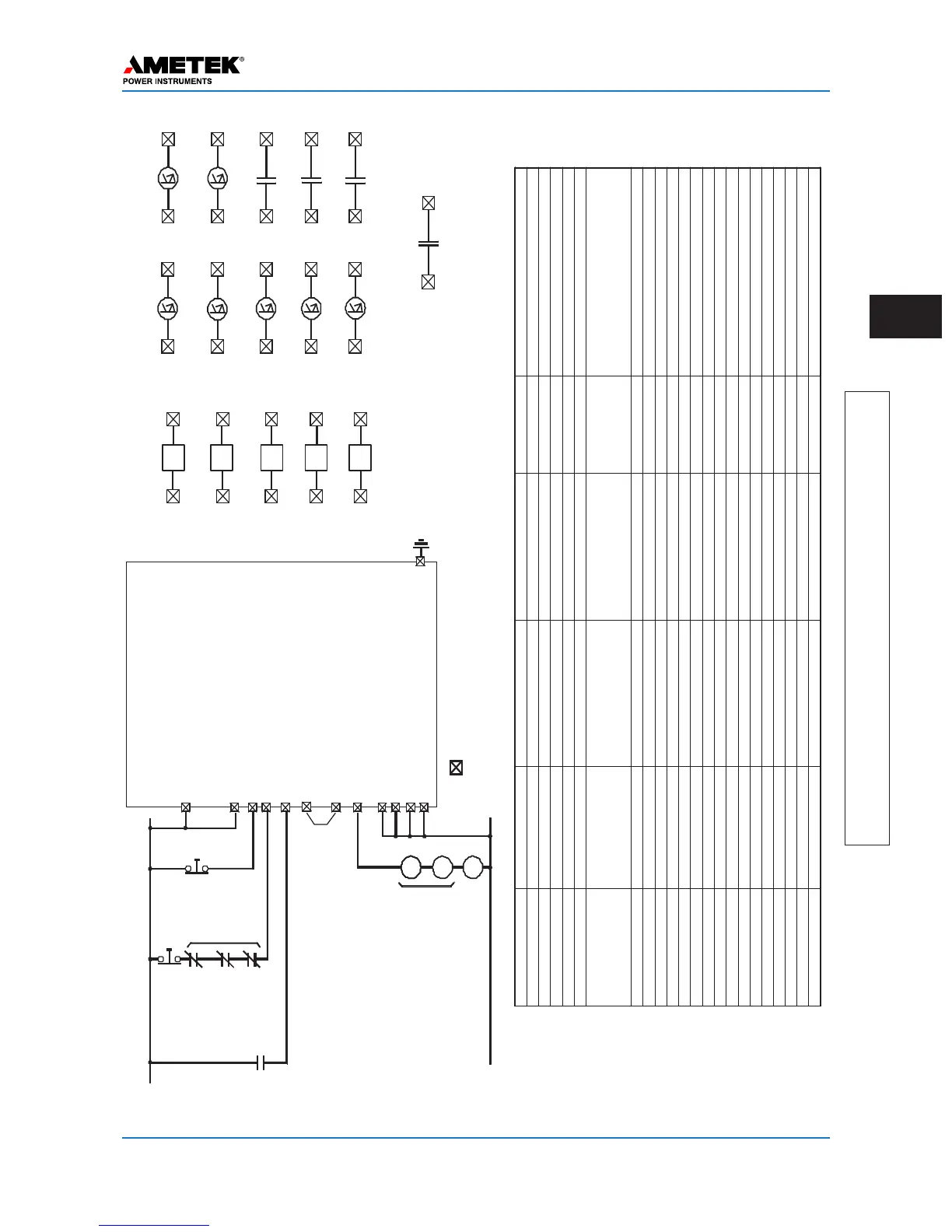
UPLC
Universal
PowerLine
Carrier
C
A
R
R
I
E
R
A
U
X
.
R
E
L
A
Y
B
A
T
T
E
R
Y
P
O
S
I
T
I
V
E
C
A
R
R
I
E
R
S
T
O
P
+
R
R
A
M
A
0
–
3
0
m
A
0
–
3
0
0
m
A
C
A
R
R
I
E
R
L
O
W
L
E
V
E
L
T
E
S
T
C
A
R
R
I
E
R
H
I
G
H
L
E
V
E
L
T
E
S
T
C
A
R
R
I
E
R
S
T
A
R
T
N
E
G
A
T
I
V
E
B
A
T
T
E
R
Y
Module Function SoftwareSelection HardwareSelection Labelonboard Recommendation
Backplane CoaxSetting 2wire/4wire JMP3/JMP5 2Wire
#ofP
As
1P
A/2P
A
JMP2/JMP6 Perfactory
CoaxImpedance 50/75ohms JMP1/JMP4 50ohms*
PowerSupply Power PwrOn/ PwrOf
f
JMP3 PwrOn
AlarmContact NO/NC JMP1/JMP2 PerEngineering
AuxPowerSupply Holdingcurrent 20mA/200mA 8V(200mA)or
46/20V(20mA)
JMP1/JMP2Percarrierrelay
requirement
(JMP3isusedonlyfor46/20Voutputs
whenJMP1/JMP2isin46/20Vposition)
Input/Output
Input1 CarrierStart RemovalofV
oltage
15/48/125/250Vdc Input1 StationBattery
Input2 CarrierStop ApplicationofV
oltage
15/48/125/250Vdc Input2 StationBattery
Input3 LowLevelKey RemovalofV
oltage
15/48/125/250Vdc In put3 StationBattery
Input4 15/48/125/250Vdc Input4 PerEngineering
Input5 15/48/125/250Vdc Input5 PerEngineering
LL
Output1
Blocking NO 0.1/1.0
A
LL0 1 1.0
A
LL
Output2
0.1/1.0
A
LL0 2 PerEngineering
LL
Output3
0.1/1.0
A
LL0 3 PerEn gineering
LL
Output4
0.1/1.0
A
LL0 4 PerEngineering
LL
Output5
0.1/1.0
A
LL0 5 PerEngineering
LL
Output6
0.1/1.0
A
LL0 6 PerEngineering
LL
Output7
0.1/1.0
A
LL0 7 PerEngineering
LL
Output8
NO/NC LL0 8 PerEngineering
LL
Output9
NO/NC LL0 9 PerEngineering
LL
Output10
General
Alarm
NO NO/NC Ll10 PerEngineering
*Orperengineering
’
srecommendation
Inputs
Carrier
Start
Carrier
Stop
Low
Level
IN 1
IN 2
IN 3
IN 4
4
IN 5
LowLevelOutputs
TB5-10
TB5-9
TB5-8
TB5-7
TB5-6
TB5-5
TB5-4
TB5-3
TB5-2
TB5-1
TB1-6
TB1-5
TB4-10
TB4-9
TB4-8
TB4-7
TB4-6
TB4-5
TB4-4
TB4-3
TB4-2
TB4-1
TB3-10
TB3-9
TB3-8
TB3-7
TB3-6
TB3-5
TB3-4
TB3-3
TB3-2
TB3-1
Gen
Alarm
PS
Alarm
LL
BlockingOutput
01
LL 02
LL 03
LL 04
LL
NOTES:
1.
Allcontactsarelinkselectablefornormallyopenorclosed.
05
LL06
LL07
LL08
LL09
LL10
 Loading...