Page 3–16
UPLC-II™ System Manual
3.5 FSK Mode Protective Relay
Applications
The UPLC-II™ carrier set is particularly suitable
for the following types of protective relay sys-
tems:
• Directional Comparison Unblocking
• Permissive Overreaching Transfer Trip
(POTT)
• Permissive Underreaching Transfer Trip
(PUTT)
• Dual Phase Comparison Unblocking
• Segregated Phase Comparison Unblocking
• Direct Transfer Trip
3.5.1 Directional Comparison
Unblocking
The Directional Comparison Unblocking systems
transmit a continuous blocking signal, except dur-
ing internal faults. The channel is generally a
Frequency-Shift Keyed (FSK) Power-Line
Carrier. For an internal fault, the FSK transmitter
is shifted to the “unblock” frequency. The trans-
mitted power in many applications is normally 1
W, boosted to 10 W during unblock operation.
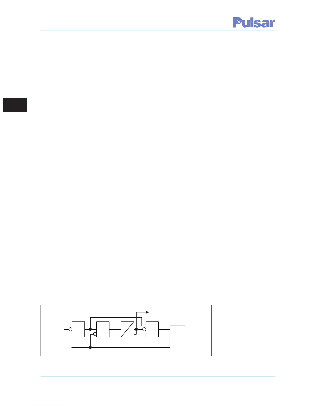
The frequency-shift channel is monitored continu-
ously to prevent tripping when a loss of channel
occurs. The carrier receiver logic is shown in
Figure 3–8. Under normal conditions, a block fre-
quency is transmitted and OR-1 has no input.
Because AND-1 and AND-2 are not satisfied, OR-
2 is not energized. For an internal fault, the block
frequency is removed. Assuming that the unblock
signal is shorted out by the fault, OR-1 provides a
direct input to AND-2 to satisfy its input require-
ments for 150 ms. AND-2 inputs to OR-2 to oper-
ate the RR or to provide input to the AND shown
in Figure 3–8. Without an unblock signal, 150 ms
is allowed for tripping. After this period, lock out
is initiated as one of the inputs to AND-2 is
removed. This resets the RR or removes the input
to AND. If the unblock signal is received, it inputs
directly to OR-2 to energize the RR or to provide
input to AND. The unblock signal also removes an
input to AND-1 to stop the timer. A channel failure
(no block or unblock signal) provides input to
AND-1 and, after 150ms, locks out the relaying
and triggers an alarm. The operation of the scheme
shown in Figure 3–9 is given in Table 3–4 for
external and internal faults. The phase and ground
trip fault detectors at both stations must operate
for all internal faults; that is, they must overreach
the remote bus.
The dependability and security of Directional
Comparison Unblocking systems make them the
most attractive of the protective schemes for trans-
mission lines using Power-Line Carrier channels.
Over-tripping is avoided by continuous blocking
and continuous channel monitoring. Only an
external fault within a certain time delay after
channel failure can result in over-tripping. This
time is selectable from 0-500ms.
The scheme is most appropriate for two-terminal
lines, but is applicable to multi-terminal lines.
Separate channels are required between each ter-
minal and the remote terminal(s). A sample
schematic is shown in Figure 3–23, near the end
of this chapter.
You may conserve frequency spectrum by using a
narrow band frequency shift carrier, but at the
expense of channel speed.
Another consideration is
an open breaker situation.
When the remote breaker
is open for an extended
period of time, the relay
system must be able to
trip. The remote relay sys-
tem sends a trip signal
when detecting a remote
Block
Frequency
Unblock(Trip)
Frequency
Lockout
(0=disabled)
ToRRor
AND
AND
2
AND
1
OR
2
0-500
ms
0
OR
1
Figure 3–8. Simplified Unblock Receiver Logic
 Loading...