January 2016 Page 3–17
Chapter 3. Applications
3
Breaker1 TripFaultDetectors(P
1
)
Breaker2 TripFaultDetector(P
2
)
ProtectedLine
G
H
F
I
F
E
PowerLineCarrier
Channelf
1
(GtoH)
PowerLineCarrier
Channelf
2
(HtoG)
1 2
RR
P
Channel
Signal
Receiver
(F
1
atH,
F
2
atG)
RR
Trip
Coil
52a
ContactLogic(per Terminal)
Key Transmitter
toUnblock
Timer
P
Trip
Unblock
(SeeFigure2-1)
AND
X
O
SolidStateLogic(per Terminal)
Note:(X)Normally4Ms.
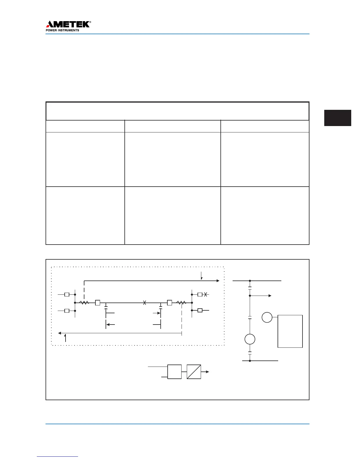
Figure 3–9. Basic Logic Diagrams for Directional Comparison Unblocking
OPERATION FOR EXTERNAL AND INTERNAL FAULTS
Internal (F
I
) P
1
operates.
f
1
channel to unblock.
Loss of block and/ or receipt
of unblock (f
2
) operates RR
or inputs AND.
Trip.
P
2
operates.
f
2
channel shifts to unblock.
Loss of block and/or receipt
of unblock (f
1
) operates RR
or inputs AND.
Trip.
Type of Fault Events at Station G Events at Station H
Table 3–4. Operation of the Directional Comparison Unblocking Scheme
External (F
E
) P
1
operates.
f
1
channel shifts to unblock.
f
2
channel continues to
block.
No trip.
P
2
does not see fault.
Loss of block and/or receipt
of unblock (f
1
) operates RR
or inputs AND.
No trip.
open breaker. If this remote signal is received for 1,000 ms (1 sec) or longer, the carrier receiver logic inter-
p
rets this as an open breaker and allows the local end to trip whenever the local relays detect a fault.
An older system (STU unblock) is shown in Figure 3–24a & 24b, near the end of this chapter.
 Loading...