Page 2–12
UPLC-II™ System Manual
FREQSEL
PA OK
LE1
TP11
PA INDC
LED
TEST
POINT
ON
OFF
L4
NottoScaleforReferenceOnly
ComponentSide
Figure 2–5. Power Amp Jumper Location
2.4.2 Power Amp Module
Description:
The Power Amp (PA) input comes from the trans-
mit portion of the Transceiver card and its output
goes to the backplane coax connector and boosts
the signal level as high as 10W max continuously
depending on the software setting. A redundant PA
can be plugged into the chassis to give up to 20 W
output. The PA contains 2 transmit meters, a
Forward Power level meter and a Reflected Power
percentage meter. The levels are displayed on the
front display as well as the home web page. The for-
ward power level meter only looks at power going
out to the coax. It is in a control loop with the
Transceiver and automatically adjusts the output
power to the correct level when the UPLC-II™’s
output level is calibrated. The reflected power
meter tracks the TX frequency and only looks at
any power coming back into the output of the PA
which falls within the narrowband (less than 500
Hz away from the transmit frequency) of the fre-
quency selective circuit of this meter. So this meter
reads accurately in the presence of high level inter-
fering signals from transmitters elsewhere on the
power line. The PA module is hot swappable.
Customer interface points:
• PA OK LED (LE1) – Indicates the status of
the Power Amp (PA). It monitors that on-
board dc voltages are within specifications
and that the PA is actually amplifying the
signal as it should. When one of these 2
parameters is bad, the LED goes off.
• PA IN DC (TP11) – A convenient test point
for measuring input signal level to the PA
from the Transmitter. The level is a dc volt-
age that is proportional to input signal
strength. Normal level is 0.35Vdc for 1W
transmit and 1.0Vdc for 10W transmit. Level
must be measured between TP11 and the
chassis itself as a ground reference.
• FREQ SEL Jumper (JMP1/2) – Normally set
to the ON position for UPLC-II™ but if the
power amp is put into a UPLC™ this jumper
has to be set to the OFF position. It enables
the frequency selectivity feature of the
reflected power meter in a UPLC-II™.
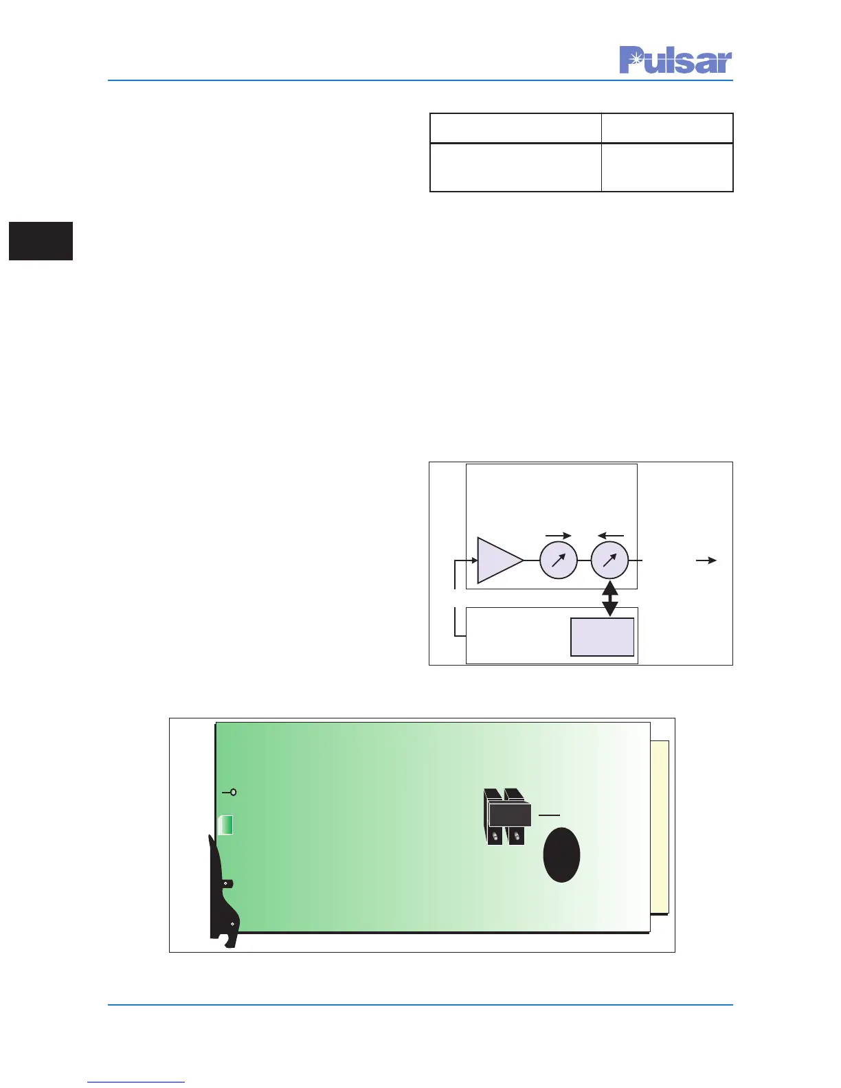
Power Ampwith
FrequencySelectivity
AMP
TRANSCEIVER
J1Coax
Freq.
Selectivity
Function
TXFWD
PWR
TXREFL
PWR
TX
Description Part Number
Power Amp (PA) Module CU20-PA1MN-002
with Freq. Selectivity
Figure 2–6. Power Amp Block Diagram
 Loading...