Page 5–34
UPLC-II™ System Manual
5.10 Home Page
The home page (Fig. 5–17) shows the general status
and settings of the unit at the time the home page
was requested by your browser, as well as other
information. In the main blue bar at the top of the
page is the date and time when the web page was
requested as well as the status of whether or not the
unit is time synched to an IRIG-B signal. In addi-
tion, two title lines which identify the unit to which
you are connected are shown, provided this text
string has been set. The main blue bar on the left of
the screen shows the IP address of the unit connect-
ed, the current configuration it is set for and the cat-
alog number of the unit at the bottom. Also it shows
all the menu buttons from which you can choose
based on the user log-in & configuration setting.
Following are the 3 main sections to the home page.
1. Settings Table
• Shows the fixed basic settings (com-
plete settings are viewed on settings
pages) which only change if you
change the settings
• Shows RX sensitivity which changes
only after each calibration of the
receiver to the remote transmitter. This
is the minimum level at which the RX
will work. (See Table 5–17 for RX sen-
sitivity levels corresponding to certain
RX levels at which calibration was per-
formed. The following figure provides
an explanation of RX Sensitivity, Fade
Alarm, and Fade Margin.)
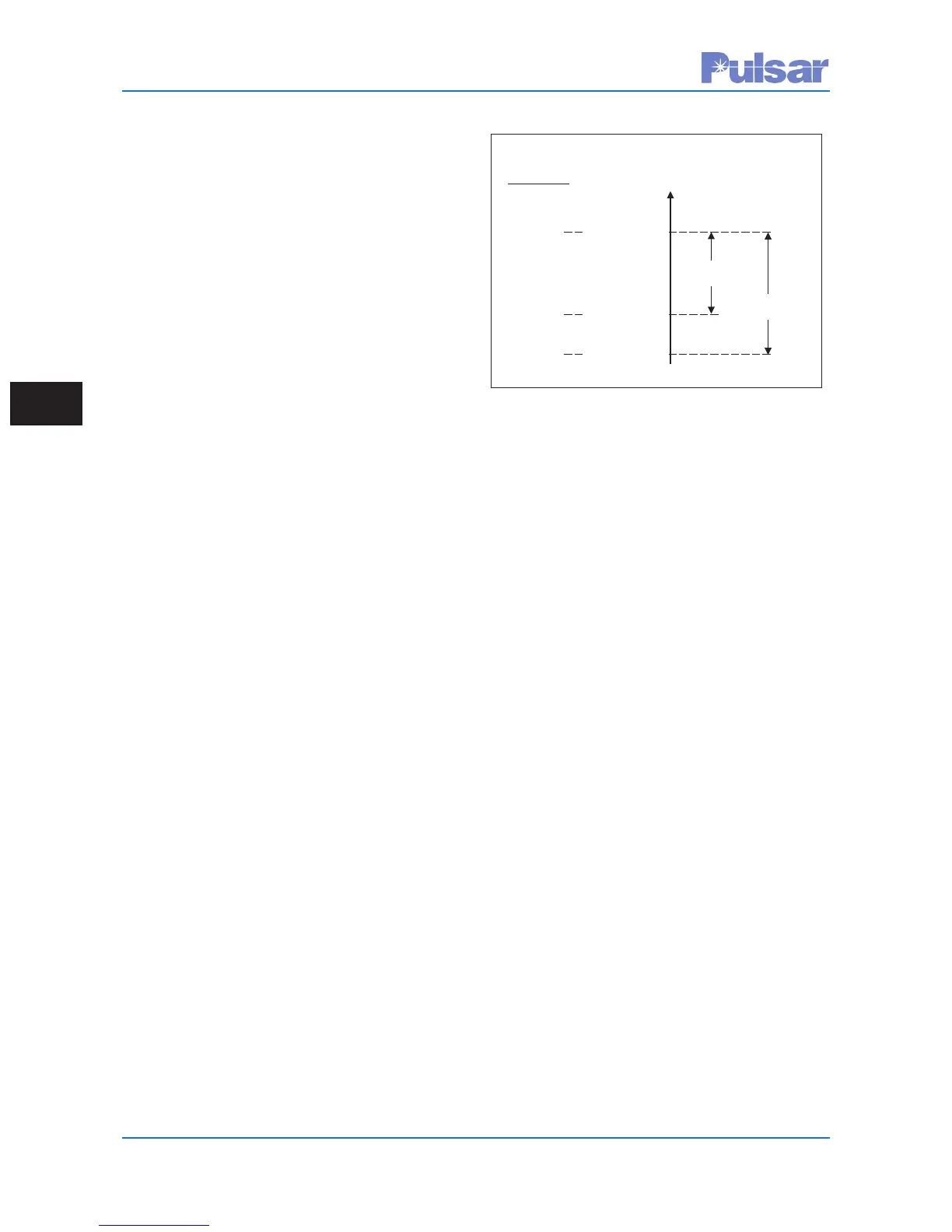
RX Fade Alarm & Fade Margin
2. Status Table *
• Shows actual measured TX / RX levels
(Note: The RX level is only accurate
after calibration of the receiver.)
• Shows Keyed State of TX and RX
Signal State
• Shows actual measured TX Reflected
Power percentage and RX fade margin,
which should always be equal to the
Fade Margin setting above in the
Settings Table after RX calibration.
• “Display Watt/Volts” (or dBm/db) but-
ton to the right allows for changing the
units displayed for these measured val-
ues
3. Alarm LEDs * (Green circle = Healthy, Red
triangle = Fail/Alarm, Grey circle = Option
not present)
• Shows General Alarm indicating over-
all hardware health for the entire unit.
• Shows specific alarms for Power Amp
& Power Supply modules.
• Shows 2 other configuration specific
alarms
Example
Levels
RXSignal
Level,dB
+20dBm
R
XFade Alarm
(
default=10dB)
RXFadeMargin
(default=15dB)
+10dBm
+5dBm
NormalRX
SignalLevel
(RXCal.Level)
Fade Alarm
Output
RXSensitivity
*
*
(RXstopsworking,lossofgoodchanneloutput)
*This information is updated about every 15 sec
or when the browser window is manually refreshed.
 Loading...