January 2016 Page 5–37
Chapter 5. Installation/Commissioning Procedure
5
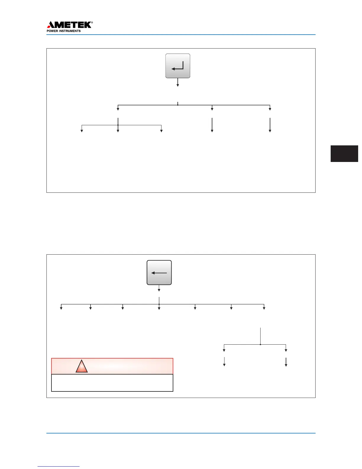
EnterPassword:
US1NEM9AFSX
(11DigitCatalogNumberisDisplayed)
1.Settings
ON/OFFMode
FSKMode|2F/4F FSKMode|3F
1. TXFreq.
2.RXFreq.
3.Bandwidth
4.LevelDisplay
dBorV/W
1. TXFreq.
2.RXFreq.
3.RXBandwidth
4.RXShift
5. TXBandwidth
6. TXShift
7.Pre-TripDelay
8.LevelDisplay
dBorV/W
1. TXFreq.
2.RXFreq.
3.RXBandwidth
4.RXShift
5. TXBandwidth
6. TXShift
7.LRPre-TripDelay
8.DTT Pre-TripDelay
9.LevelDisplay
dBorV/W
1.ChangePassword
2.IP Address
(IP,Mask,Gateway)
3.ViewMAC Address
4.ViewRevisions
(firmware,Cat#)
1. Transmitter
2.Receiver
a.RXtoDistant TX
b.RXtoLocal TX
(ON/OFFmodeonly)
3. AdjustExternalCLI
2.Configure
SET
3.Calibrate
Figure 5–19. UPLC-II™ SET Button Menu (ON/OFF & FSK)
Figure 5–20. UPLC-II™ TEST Button Menu (ON/OFF Mode Only)
1.HL Send
(High
Level TX)
****
1.Show Inputs
Refl Pwr: X% (TX Reflected Power is Displayed Only When Transmitting)
* Only available with Checkback testing facilities option.
2. Change Outputs
12345
Inputs:00000
(1=Volt Applied
0=No Volt Applied)
Outputs
EM1234 LL1234567890
0000 0101010101
(1=Output Closed,
0=Output Open)
2. LL Send
(Low
Level TX)
3. CB Initiate
(Start
CB Test)
4. Loopback
Initiate
(Turns On
Remote
Transmitter)
5. Reset CB
Alarms
(Clear CB
Alarms)
6. Reset CB
Recovery
(Clear CB
Recovery
Mode)
7. Test I/O
(Test Inputs
& Outputs)
TEST
5.11.4 Test Button Menu
See Figs. 5–20, 21, 22. Pressing the TEST or Left arrow allows you to test the functionality of the unit. It
also shows the TX reflected power percentage on the top line above the TEST menu. This TEST menu can
be password-protected if desired (see Figure 5–3).
!
CAUTION
Be sure all trip circuits are open
before toggling outputs in test menu.
 Loading...