January 2016 Page 7–3
Chapter 7. Communication Protocols
7
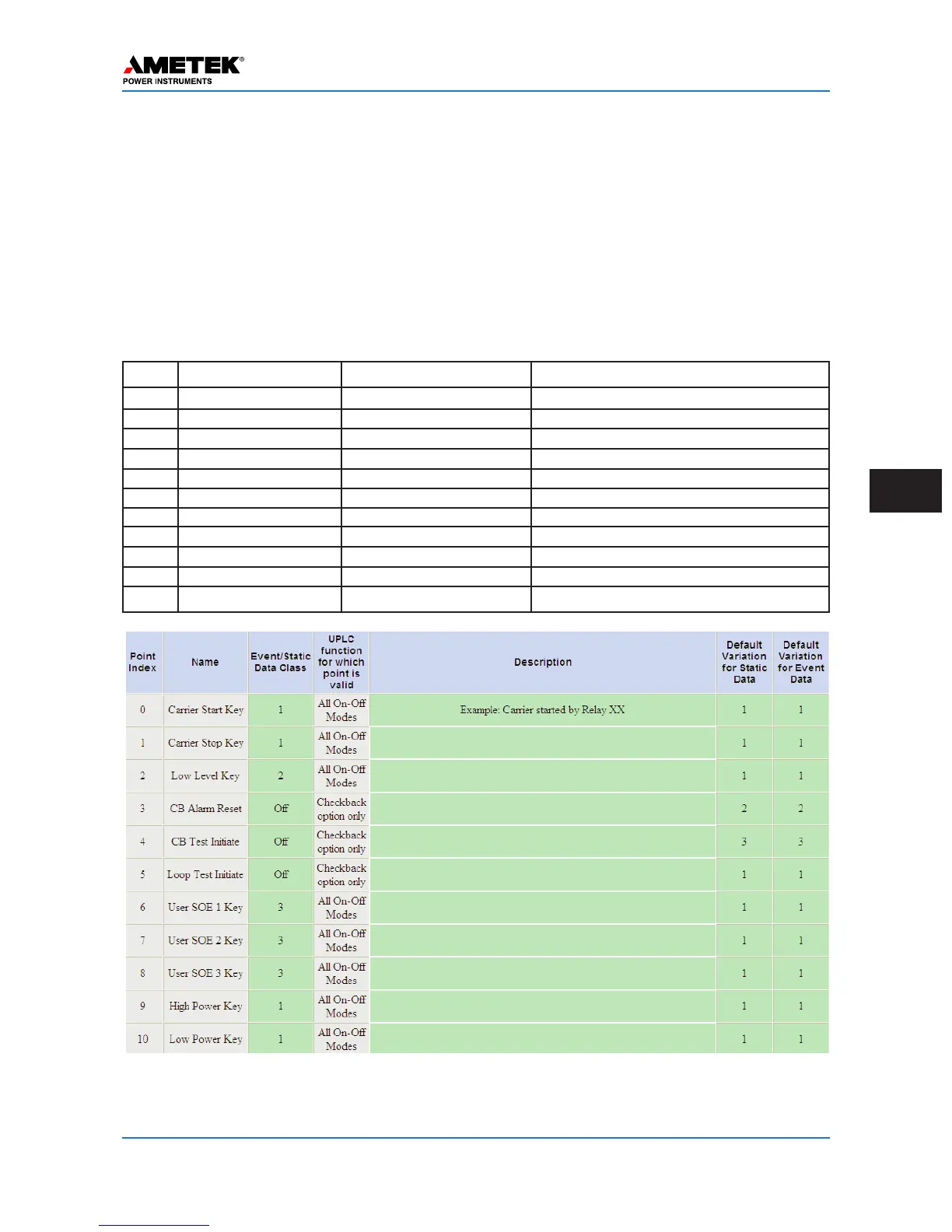
Figure 7–3. DNP Binary Inputs / UPLC-II™ Inputs Settings Page
(Admin > Protocol > DNP > UPLC-II™ Inputs)
Table 7–1. UPLC-II™ Inputs – DNP Points (ON/OFF Mode)
Point Name Setting Mode Definition
0 Carrier Start Key All ON/OFF Modes Carrier Start Input has been Keyed
1 Carrier Stop Key All ON/OFF Modes Carrier Stop Input has been Keyed
2 Low Level Key All ON/OFF Modes Low Level Keying Input has been Keyed
3 CB Alarm Reset Checkback Option Only Checkback Alarms have been Reset
4 CB Test Initiate Checkback Option Only Checkback Test has been Initiated
5 Loop Test Initiate Checkback Option Only Loop Back Test has been Initiated
6 User SOE 1 Key All ON/OFF Modes SOE Event 1 Input has been Keyed
7 User SOE 2 Key All ON/OFF Modes SOE Event 2 Input has been Keyed
8 User SOE 3 Key All ON/OFF Modes SOE Event 3 Input has been Keyed
9 High Power Key All ON/OFF Modes High Power Level has been Keyed
10 Low Power Key All ON/OFF Modes Low Power Level has been Keyed
7.2 DNP Binary Inputs (UPLC-II™
Inputs)
The UPLC-II™ has five physical binary inputs that
can be assigned numerous functions chosen from a
selection menu. The following tables include all
possible input selections for the UPLC-II™
ON/OFF and FSK modes. Since there are only five
inputs and many possible selections, at any given
time some of these selections will be unassigned or
not used. The on-line bits of these unassigned selec-
tions will be set to zero.
 Loading...