Page 2–2
UPLC-II™ System Manual
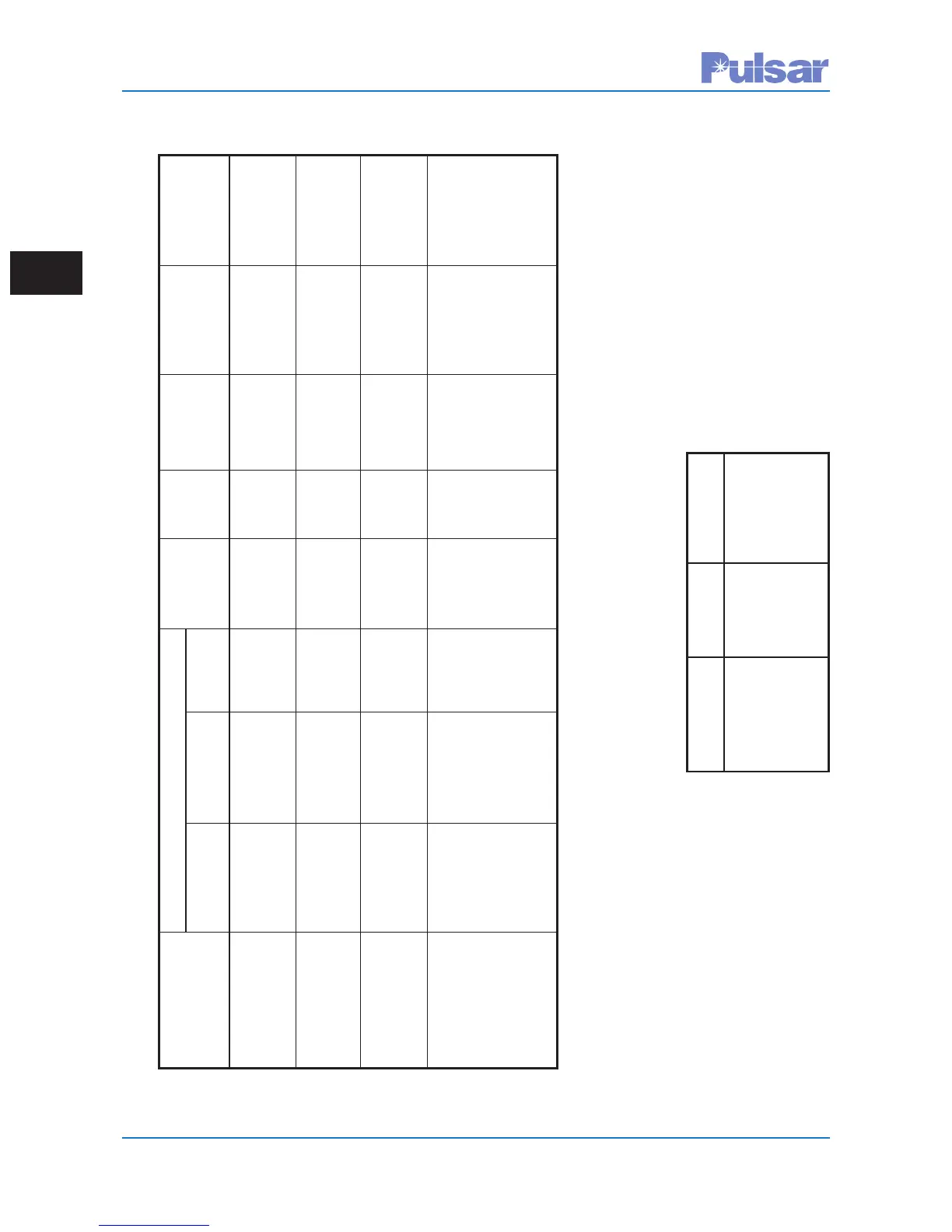
Table 2–5. Keying Input Ratings
(All Inputs Current Limited &
Non-Polarity Sensitive)
Nominal Min Keying Max Current
Input Voltage Voltage Draw
15 Vdc 10 Vdc 5 mA
48/60 Vdc 38 Vdc 5 mA
110/125 Vdc 70 Vdc 5 mA
220/250 Vdc 150 Vdc 5 mA
Table 2–4. Output Ratings (All Outputs Non-Wetted & Non-Polarity Sensitive)
Output Max Current at @ 250 Vdc N.O. / N.C. Nominal Voltage Max Max
(Terminal Make & Carry Make & Carry Interrupt Selectable Voltage Range Operate Dropout
Block) Continuous Short Term Drop Time Time
Power Supply 8 A N/A 0.25 A Hardware 0 V 15-250 Vdc 15 ms 10 ms
Alarm Jumper
(TB1 or 2 - 5 & 6) (PS)
7 Low Level 0.1 / 1.0 A 6 A / 15 ms 0.1 / 1.0 A Software 2.5 V 15-250 Vdc 0.5 ms 0.5 ms
Solid State Hardware for 1 A Hardware Setting
(TB4 & 5) Selectable Setting Selectable
3 Low Level 8 A N/A 0.25 A Hardware 0 V 15-250 Vdc 15 ms 10 ms
EM Contacts Jumper
(TB5) (I/O)
4 Trip Duty 14 A 30 A / 200 ms 0.25 A Hardware 0.2 V 15-250 Vdc N.O. Contact N.O. Contact
EM Contacts w/duty cycle Jumper @ Closing = Opening =
(TB6) per ANSI (I/O) < 1 A 3 ms 5 ms
C37.90 7 V N.C. Contact N.C. Contact
@ Opening = Closing =
30 A 2 ms 4 ms
 Loading...