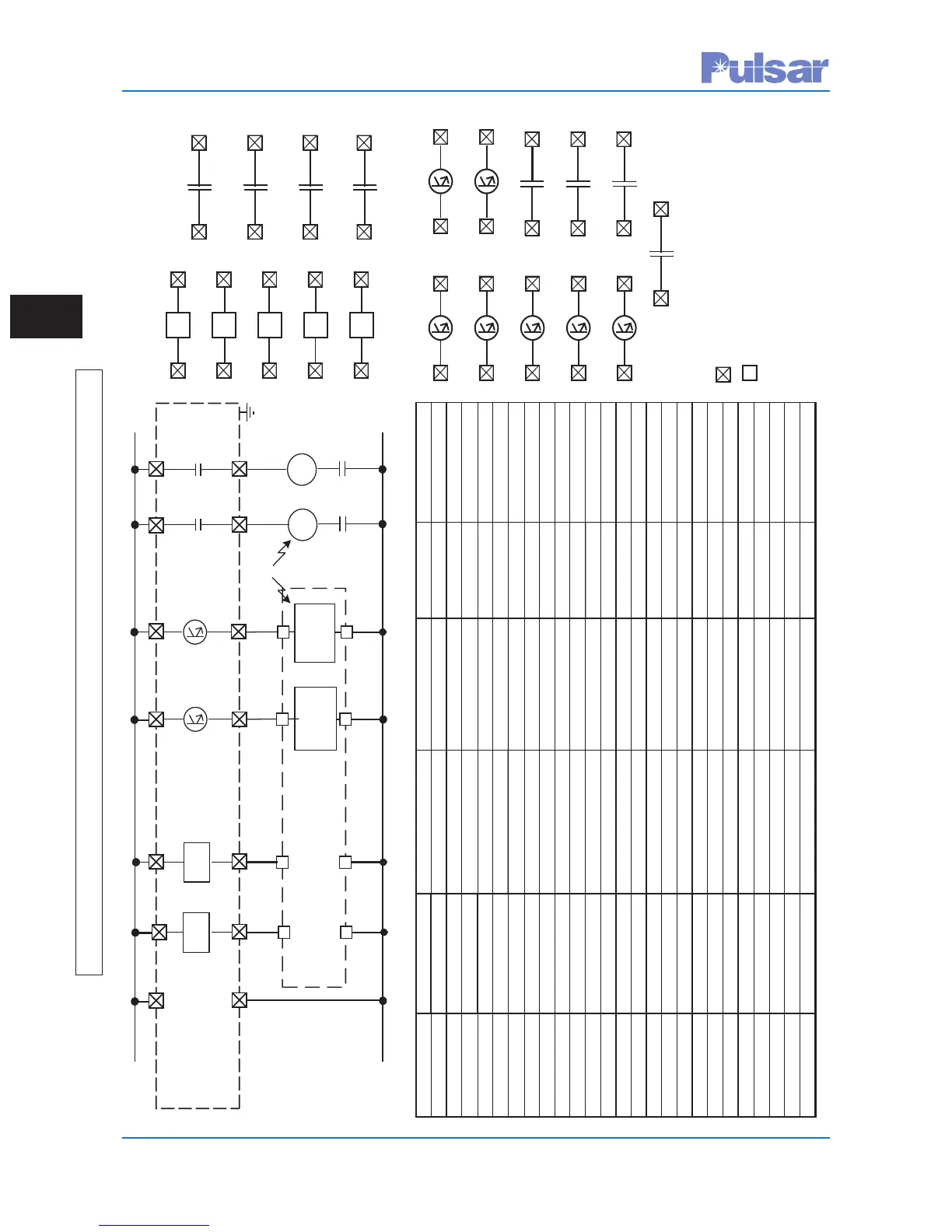
No
te: All cont
acts are link
sel
ectable for
normally op
en or
clo
sed.
TB1-1
T
B1-2
Key
A
Outp
ut
D
C Input
TB4
-9
T
B4-4
TB
3-5
TB3-10
A
Key
T
rip
A
Perm.
Input
Relay
TB4-7
TB
3-9
TB4-2
TB
3-4
BKey
Chassis Gnd
UPLC
TB6
-2
TB6-1
B
T
rip
TB3-5
TB3
-4
TB3
-9
TB3-3 TB3-8
T
B3-2
T
B3-7
TB3-1 TB3-6
TB3-10
A Key
Power Off
Inputs
IN1
TD01
TD02
TD03
TD04
IN2
IN3
IN4
IN5
B Key
TB4-5
TB5-5
T
B4-4
T
B5-4T
B4-9
T
B5-9
TB
4-3
TB5
-3
TB
4-8
TB5
-8
TB4-2
TB5-2
TB4-7
TB5-7
TB4
-1
TB5-
1
TB4
-6
TB5-
6
TB4-1
0
TB5-1
0
A Guard
A Trip
Go
od Channel
Noise
R
F Alarm
LowLevelOutputs
PS Alarm
T
B1-5
T
B1-6
B Gua
rd
B Trip
TX Shift
to B
T
X Shift to A
General Alarm
Jumper
T
able
BatteryPositive
BatteryNegative
T
B6-7
T
B6-8
TB6-5 TB6-6
TB6-3 TB6
-4
TB6-1 TB6-2
T
ripDutyOutputs
A Guard
A Trip
B Gua
rd
B Trip
A
T
rip
B
T
rip
Key B
Outpu
t
T
ripB
Perm.
Input
TB6
-6
TB6-5
A
T
rip
52
TC
52A
52
TC
52A
OR
Module Function SoftwareSelection HardwareSelection Label Recommendation
Backplane CoaxSetting 2wire/4wire JMP3/JMP5 4wire
#ofP
As
1P
A/2P
A
JMP2/JMP6 Perfactory
CoaxImpedance
50 W/75 W
JMP1/JMP4
50 W
*
PowerSupply Power PwrOn/PwrOf
f
JMP3 PwrOn
AlarmContact NO/NC JMP1/JMP2 Perengineering
Input/Output StationBattery
Input1 A Key ApplicationofV
oltage
15/48/125/250Vdc Input1 Perengineering
Input2 B
Key
ApplicationofV
oltage
15/48/125/250Vdc Input2 Perengineering
Input3 PowerOf
f
ApplicationofV
oltage
15/48/125/250Vdc Input3 Perengineering
Input4 15/48/125/250Vdc Input4 Perengineering
Input5 15/48/125/250Vdc Input5 Perengineering
LL
Output1
A
Guard
0.1/1.0
A
LL01 Perengineering
LL
Output2
A
T
r
ip 0.1/1.0
A
LL02 Perengineering
LL
Output3
BGuard 0.1/1.0
A
LL03 Perengineering
LL
Output4
B
T
rip
0.1/1.0
A
LL04 Perengineering
LL
Output5
GoodChannel 0.1/1.0
A
LL05 Perengineering
LL
Output6
Noise 0.1/1.0
A
LL06 Perengineering
LL
Out
put7 TXShift A 0.1/1.0
A
LL07 Perengineering
LL
Output8
TXShift B NO/NC LL08 Perengineering
LL
Output9
RF
Alarm
NO/NC LL09 Perengineering
LL
Output10
General
Alarm
NO/NC LL10 Perengineering
TDOutput1 A
Guard
NO/NC TD01 NO
TDOutput2 A
T
rip
NO/NC TD02 NO
TDOutput3 B
Guard
NO/NC TD03 NO
TDOutput4 B
T
rip
NO/NC TD04 NO
*Orperengineering
’
srecommendation
UPLC Ter
minals
Relay
Terminals
TB4-5+10
TB4-4+9
TB4-3+8
TB4-2+7
TB4-1+6
TB5-5+10
TB5-4+9
TB5-3+8
TB5-2+7
TB5-1+6
TB6-7+8
TB6-5+6
TB6-3+4
TB6-1+2
LL01
LL06
LL02
LL07
LL03
LL08
LL04
LL09
LL05
LL10
 Loading...