January 2016 Page 3–35
Chapter 3. Applications
3
Note:
All contact
s are link
select
able for nor
mally open
or clos
ed.
TB1-1
T
B1-2
K
eying Outp
ut
D
C Input
TB
4-9
TB4-4
TB3-5
T
B3-10
LR
T
rip
cc
Relay
Trip Per
m. Input
TB4-7
LOR
TB3
-9
T
B4-2
TB3
-4
DTT
T
rip
Key
T
ransmitter
Down
Key
T
ransmitter
UP
ChassisGnd
UPLC
TB6-1
52
T
C
TB
6-2
52a
LOR
DTT
T
rip
TB3-5
TB3-4 TB3-9
TB3-3 TB3-8
TB3
-2
TB3
-7
TB3-1 TB3-6
TB3-10
LR Trip Key
Power Off
Inputs
IN1
TD01
LL01
LL06
LL02
LL07
LL03
LL08
LL04
LL09
LL05
LL10
PS
Alarm
TD02
TD03
TD04
IN2
IN3
IN4
IN5
DTT Key
TB4-5
TB5-5
T
B4-4
T
B5-4T
B4-9
T
B5-9
TB
4-3
TB5
-3TB
4-8
TB5
-8
TB4-2
TB5-2
TB4-7
TB5-7
TB4
-1
TB5-
1TB4
-6
TB5-
6
TB4-1
0
TB5-1
0
L
R Guard
LR Trip
Go
od Channel
Noise
R
F Alarm
LowLevelOutputs
T
B1-5
T
B1-6
DTT Gu
ard
DTT Trip
TX Shift
Lo
TX Shift
H
igh
General Alarm
Jumper
T
able
OR
BatteryPositive
BatteryNegative
DTT
Keying
TB6
-7
TB6
-8
TB6-5 TB6-6
TB6-3 TB6-4
TB6-1 TB6-2
T
ripDutyOutputs
LR Guard
LR
Trip
DTT Guard
DTT Trip
Module Function SoftwareSelection HardwareSelection Label Recommendation
Backplane CoaxSetting 2wire/4wire JMP3/JMP5 4wire
#ofP
As
1P
A/2P
A
JMP2/JMP6 Perfactory
CoaxImpedance
50 W/75 W
JMP1/JMP4
50 W
*
PowerSupply Power PwrOn/PwrOf
f
JMP3 PwrOn
AlarmContact NO/NC JMP1/JMP2 Perengineering
Input/Output StationBattery
Input1 LR T
ripkey
ApplicationofV
oltage
15/48/125/250Vdc Input1 Perengineering
Input2 DTT
Key
ApplicationofV
oltage
15/48/125/250Vdc Input2 Perengineering
Input3 PowerOf
f
ApplicationofV
oltage
15/48/125/250Vdc Input3 Perengineering
Input4 15/48/125/250Vdc Input4 Perengineering
Input5 15/48/125/250Vdc Input5 Perengineering
LL
Output1
LRGuard
TB4-5+10
TB4-4+9
TB4-3+8
TB4-2+7
TB4-1+6
TB5-5+10
TB5-4+9
TB5-3+8
TB5-2+7
TB5-1+6
TB6-7+8
TB6-5+6
TB6-3+4
TB6-1+2
0.1/1.0
A
LL01 Perengineering
LL
Outp
ut2 LR
T
rip
0.1/1.0
A
LL02 0.1
A
LL
Output3
DTT
Guard
0.1/1.0
A
LL03 Perengineering
LL
Output4
DTT
T
rip
0.1/1.0
A
LL04 1.0
A
LL
Output5
GoodChannel 0.1/1.0
A
LL05 Perengineering
LL
Output6
Noise 0.1/1.0
A
LL06 Perengineering
LL
Output7
TXShiftHigh 0.1/1.0
A
LL07 Perengineering
LL
Output8
TXShiftLo NO/NC LL08 Perengineering
LL
Output9
RF
Alarm
NO/NC LL09 Perengineering
LL
Output10
General
Alarm
NO/NC LL10 Perengineering
TDOutput1 LRGuard NO/NC TD01 NO
TDOutput2 LR
T
rip
NO/NC TD02 NO
TDOutput3 DTT
Guard
NO/NC TD03 NO
TDOutput4 DTT
T
rip
NO/NC TD04 NO
*Orperengineering
’
srecommendation
UPL
C Terminals
Relay
Terminals
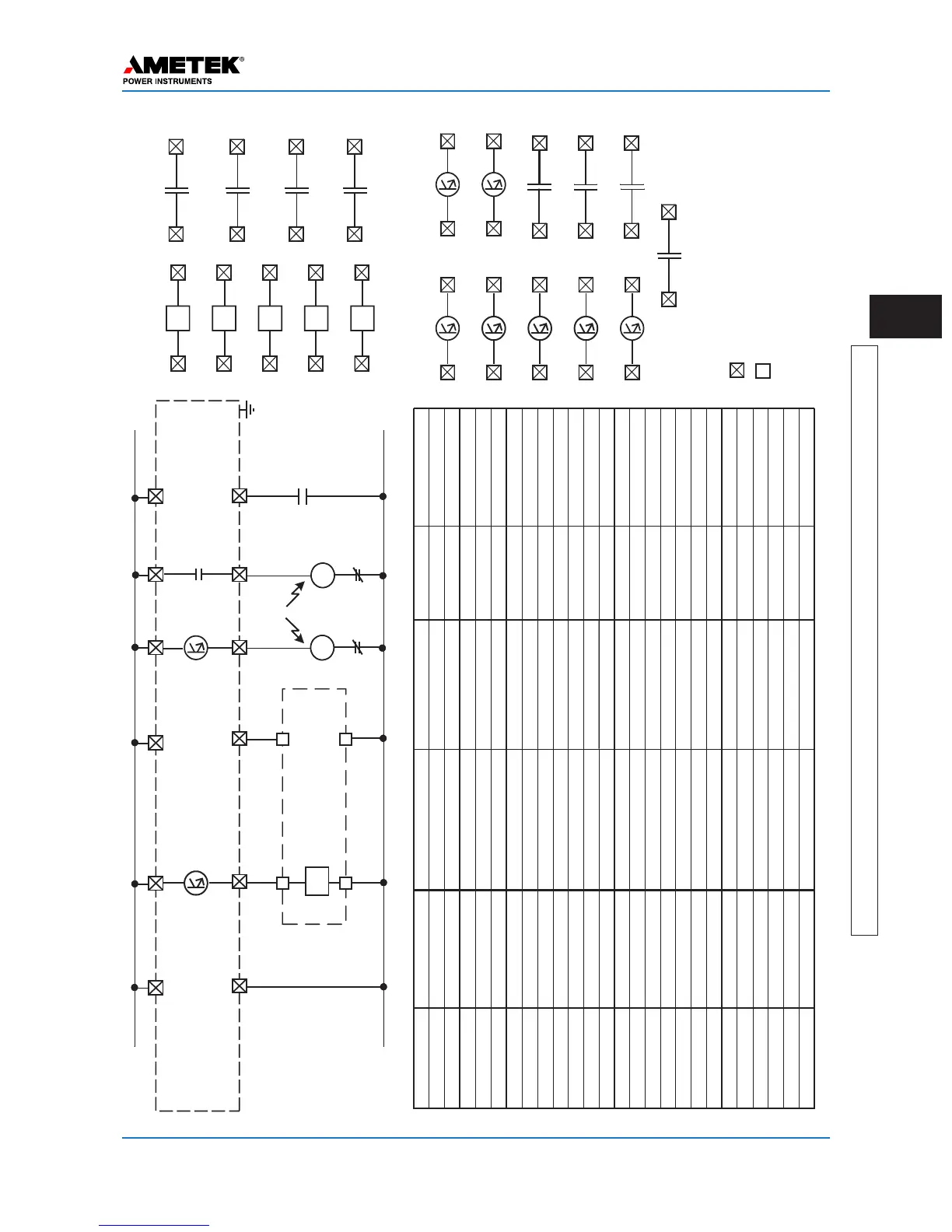
Figure 3–27. FSK Mode, 3-Frequency, (Unblock & DTT) - Connections/Settings
UPLC-II

 Loading...