January 2016 Page 5–9
Chapter 5. Installation/Commissioning Procedure
5
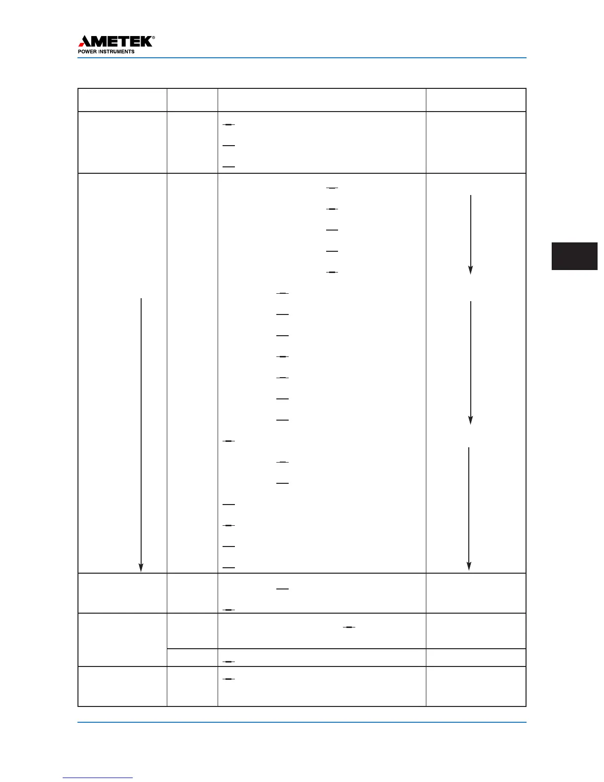
Module Jumper Selection Description
Backplane JMP1/4
√ 50Ω ___75Ω J1-TX Impedance
JMP3/5 √ 2-wire ___4-wire TX/RX Connect
JMP2/6/7 √ 1-PA ___2-PA Single/Dual PA
I/O Module INPUT 1 ___15V ___48V √ 125V ___250V Keying Voltage
INPUT 2 ___15V ___48V √ 125V ___250V
INPUT 3 ___15V ___48V √ 125V ___250V
INPUT 4 ___15V ___48V √ 125V ___250V
INPUT 5 ___15V ___48V √ 125V ___250V
LL01 ___0.1A √ 1.0A Max. Current
LL02 ___0.1A √ 1.0A
LL03 ___0.1A √ 1.0A
LL04 ___0.1A √ 1.0A
LL05 ___0.1A √ 1.0A
LL06 ___0.1A √ 1.0A
LL07 ___0.1A √ 1.0A
LL08 √ NO ___NC Contact NO/NC
LL09 ___NO √ NC
LL10 ___NO √ NC
optional TD01 √ NO ___NC
optional TD02 √ NO ___NC
optional TD03 √ NO ___NC
optional TD04 √ NO ___NC
Power Supply JMP1/2 ___NO √ NC PS Alarm Contact
JMP3 √ PWR ON ___PWR OFF PS Enable/Disable
Aux. PS JMP1/2 __46V(20mA)/20V or
√ 8V(200mA) 20mA or 200mA
(Optional for EM source, or 20V
Relay Interface) JMP3
√ 46V(20mA) or ___20V 20mA or 20V
Power Amp JMP1/2
√ ON or ___OFF TX Refl. Power
Freq. Sel. Freq. Selectivity
Hardware Jumper Settings Worksheet (Shipping Defaults shown with a √)
Output
 Loading...