January 2016 Page 7–9
Chapter 7. Communication Protocols
7
ms to see if a high speed output change occurs prior
t
o the time period. Should a high speed element
change, then the message is transmitted immediate-
ly. These are outputted via the same “GOOSE”
message. The only difference is the processing
time. The high speed GOOSE outputs are bolded in
the “Output” list below. The other outputs (as listed
in Alarms) are slow speed GOOSE elements.
Alarms
These are the data items available from the UPLC-
II™ to indicate functionality/health of the device.
These are non-protection based functions.
GeneralFail
ReflectedPowerAlarm
TransmitterKeyedState
ReceivedState
PowerAmpOneAlarm
PowerAmpTwoAlarm
FSKLowLevel
ONOFFCheckbackMajorAlarm
ONOFFCheckbackMinorAlarm
ONOFFCheckbackInRecovery
ONOFFCheckbackAutoOff
ONOFFCheckbackRecovered
ONOFFCheckbackDelayedAlarm
ONOFFCheckbackPassed
ONOFFCheckbackOff
ONOFFCheckbackInProgress
ONOFFFadeAlarm
PowerSupplyOneAlarm
PowerSupplyTwoAlarm
FSKFadeMarginAlarm
FSKFadeAlarm
FSKShiftLowFrequency
FSKShiftHighFrequency
RF Output
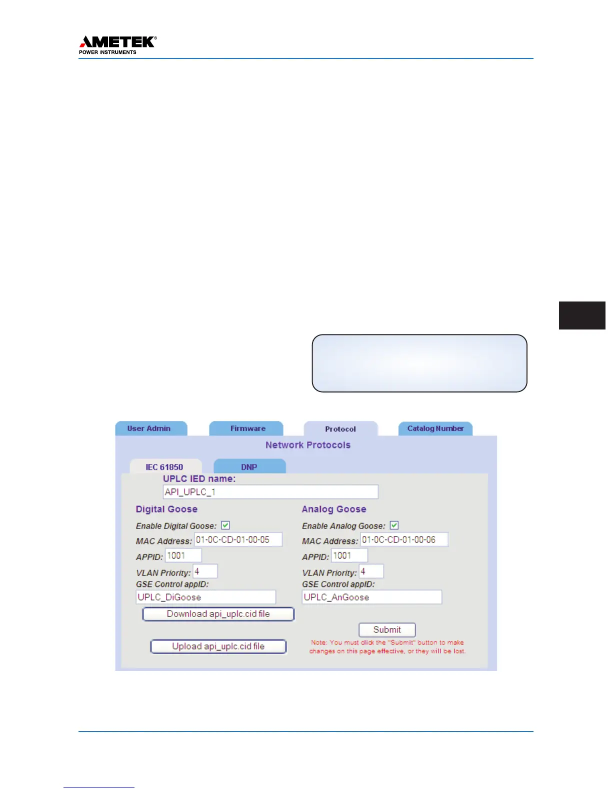
Figure 7–6. GOOSE Definitions Page
(Admin > Protocol > IEC 61850)
NOTE
For loss of goose signal data, a general
alarm output will occur and there will be a
GSDL alarm code on the front display.
 Loading...