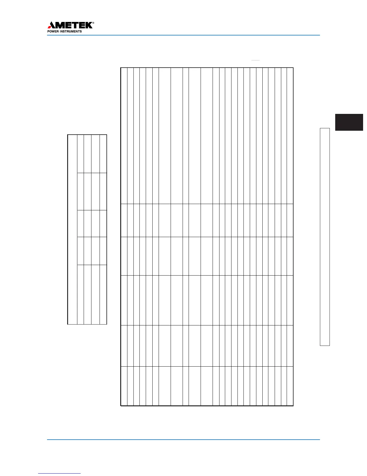
Module Function Software Selection Hardware Selection Label on board Recommendation
Backplane Coax Setting 2 wire/4 wire JMP3/JMP5 2 Wire
# of P
As
1 P
A/2P
A
JMP2/JMP6 Per factory
Coax Impedance
50 W /75 W
JMP1/JMP4
50 W
*
Power Supply Power PwrOn/ PwrOf
f
JMP3 PwrOn
Alarm Contact NO/NC JMP1/JMP2 Per Engineering
Aux Power Supply Holding current 20 mA/200 mA 8V(200 mA) or
46/20V(20 mA)
JMP1/JMP2 Per carrier relay requirement
(JMP3 is used only for 46/20V outputs when JMP1/JMP2 is in 46/20V position)
Logic Common Start/Stop
Keying Input
Enable
Input/Output
Input 1 Carrier Start Application of V
oltage
15/48/125/250 Vdc Input 1 Set to voltage setting one step below station battery
, ie
–
125 Vdc battery
, use
48 volt jumper
Input 2 Carrier S top Application of voltage 15/48/125/250 Vdc Input 2 Set to voltage setting one step below station battery
, ie
–
125 Vdc battery
, use
48 volt jumper
Input 3 Low Level Key Application of voltage 15/48/125/250 Vdc Input 3 Per Engineering
Input 4 15/48/12 5/250 Vdc Input 4 Per Engineering
Input 5 15/48/125/250 Vdc Input 5 Per Engineering
LL
Output 1
Blocking Output (NO) 0.1/1.0
A
LL01 1.0
A
LL
Output 2
0.1/1.0
A
LL02 Per Engineering
LL
Output 3
0.1/1.0
A
LL03 Per Engineering
LL
Output 4
0.1/1.0
A
LL04 Per Engineering
LL
Output 5
0.1/1.0
A
LL05 Per Engineering
LL
Output 6
0.1/1.0
A
LL06 Per Engineering
LL
Output 7
0.1/1.0
A
LL07 Per Engineering
LL
Output 8
NO/NC LL08 Per Engineering
LL
Output 9
NO/NC LL09 Per Engineering
LL
Output
10
General
Alarm
NO/NC LL10 Per Engineering
* Or per engineering
’
s recommendation
Programming /Jumper
T
able
Condition Carrier Start Carrier Stop Idle (no start/stop)
Both start & stop
V
oltage across Stop Input
15V 125V 62.5V 125V
V
oltage across Start Input
1
10V
0V 62.5V 0V
Result Start Carrier Stop Carrier Stop Carrier Stop Carrier
Conditions of UPLC-II inputs for use with KA4 electromechanical relay (Stop Priority)

 Loading...