January 2016 Page 3–11
Chapter 3. Applications
3
N
O
T
E
S
:
1
-
A
l
l
c
o
n
t
a
c
t
s
a
r
e
l
i
n
k
s
e
l
e
c
t
a
b
l
e
f
o
r
n
o
r
m
a
l
l
y
o
p
e
n
o
r
c
l
o
s
e
d
.
T
B
1
-
1
T
B
1
-
2
D
C
I
n
p
u
t
T
B
4
-
1
0
T
B
4
-
5
T
B
3
-
5
T
B
3
-
1
0
Block
cc
Relay
T
B
3
-
9
T
B
3
-
4
Carrier
Start
Carrier
Stop
ChassisGnd
UPLC-II
T
B
3
-
5
T
B
3
-
4
T
B
3
-
9
T
B
3
-
3
T
B
3
-
8
T
B
3
-
2
T
B
3
-
7
T
B
3
-
1
T
B
3
-
6
T
B
3
-
1
0
C
a
r
r
i
e
r
S
t
a
r
t
Inputs
IN 1
IN 2
IN 3
IN 4
IN 5
C
a
r
r
i
e
r
S
t
o
p
T
B
4
-
5
T
B
5
-
5
T
B
4
-
4
T
B
5
-
4
T
B
4
-
9
T
B
5
-
9
T
B
4
-
3
T
B
5
-
3
T
B
4
-
8
T
B
5
-
8
T
B
4
-
2
T
B
5
-
2
T
B
4
-
7
T
B
5
-
7
T
B
4
-
1
T
B
5
-
1
T
B
4
-
6
T
B
5
-
6
T
B
4
-
1
0
T
B
5
-
1
0
B
l
o
c
k
i
n
g
O
u
t
p
u
t
LowLevelOutputs
P
S
A
l
a
r
m
T
B
1
-
5
T
B
1
-
6
G
e
n
e
r
a
l
A
l
a
r
m
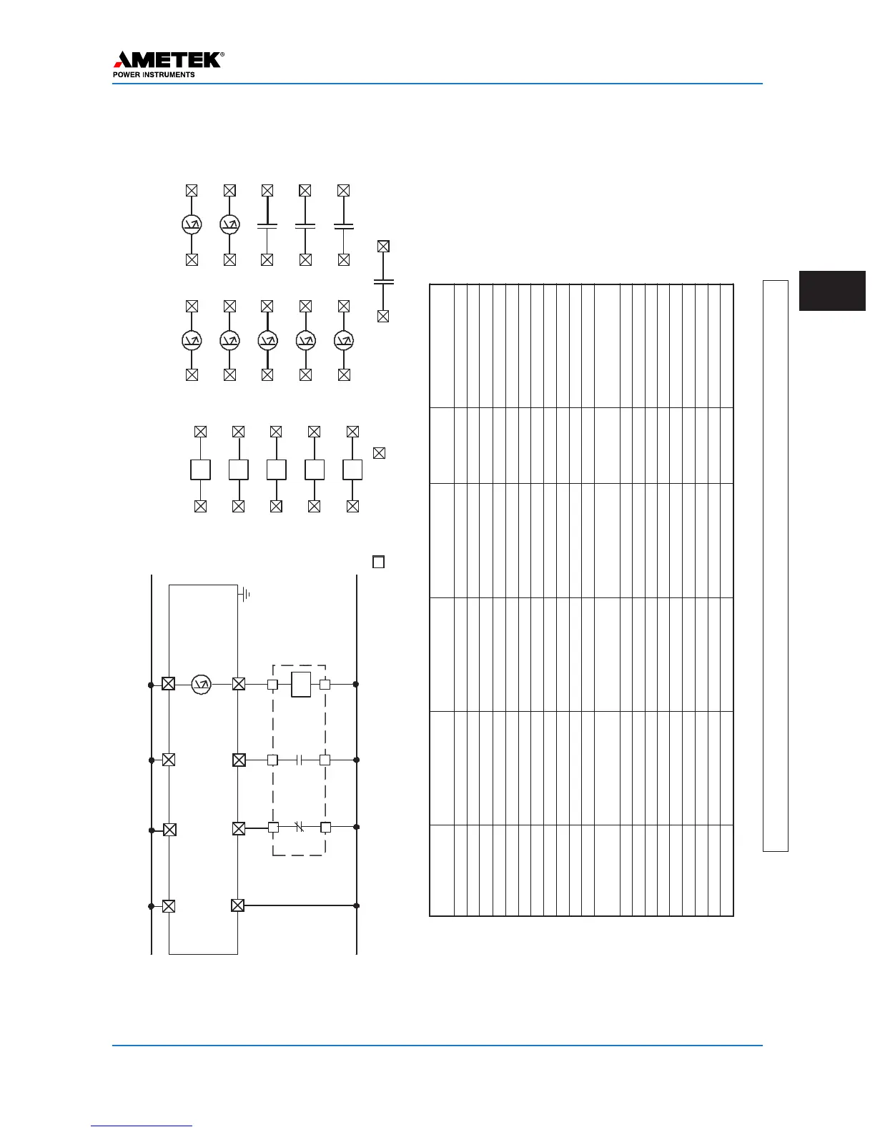
Module Function SoftwareSelection HardwareSelection Labelon
board
Recommendation
Backplane CoaxSetting ---------- 2wire/4wire JMP3/JMP5 2Wire
#ofP
As
---------- 1P
A/2P
A
JMP2/JMP6 Perfactory
CoaxImpedance ----------
50 W/75 W
JMP1/JMP4
50 W
*
PowerSupply Power ---------- PwrOn/PwrOf
f
JMP3 PwrOn
AlarmContact ---------- NO/NC JMP1/JMP2 PerEngineering
Input/Output
Input1 CarrierStart RemovalofV
oltage
15/48/125/250Vdc Input1 StationBattery
Input2 CarrierStop Applicationof
V
oltage
15/48/125/250Vdc Input2 StationBattery
Input3 (notused) 15/48/125/250Vdc Input3 PerEngineering
Input4 (notused) 15/48/125/250Vdc Input4 PerEngineering
Input5 (notused) 15/48/125/250Vdc Input5 PerEngineering
LL
Output1
Blocking
(CarrierReceived)
---------- 0.1/1.0
A
Ll01 0.1
A
LL
Output2
(notused) ---------- 0.1/1.0
A
LL02 PerEngineering
LL
Output3
(notused) ---------- 0.1/1.0
A
LL03 PerEngineering
LL
Output4
(notused) ---------- 0.1/1.0
A
LL04 PerEngineering
LL
Output5
(notused) ---------- 0.1/1.0
A
LL05 PerEngineering
LL
Output6
(notused) ---------- 0.1/1.0
A
LL06 PerEngineering
LL
Output7
(notused) ---------- 0.1/1.0
A
LL07 PerEngineering
LL
Output8
(notused) ---------- NO/NC LL08 PerEngineeri ng
LL
Output9
(notused) ---------- NO/NC LL09 PerEngineering
LL
Output10
General
Alarm
---------- NO/NC LL10 PerEngineering
*Orperengineering
’
srecommendation
Jumper
T
able
BatteryPositive
BatteryNegative
R
e
l
a
y
T
e
r
m
i
n
a
l
s
U
P
L
C
T
e
r
m
i
n
a
l
s
LL01
LL02
LL03
LL04
LL05
LL06
LL 07
LL 08
LL09
LL10
Figure 3–6. ON/OFF Mode, DCB with Microprocessor Relay – Connections/Settings

 Loading...