Installation Procedures: NXD-1200V Panels
33
NXD/T-1200V Wall/Flush Mount Touch Panel
Pre-wall Installation of the Conduit Box
Wall Mount panels (NXDs) are contained within a metallic outer housing (back box). This back box is not removed
when installing the NXD into a conduit box (CB-TP12). The back box is only removed to either gain access for the
replacement of the Memory/Compact Flash or upgrade the unit with an MB-TP Universal VESA Mounting Kit.
The CB-TP12 conduit wallbox is an optional metallic box that is secured onto stud beams prior to the installation of a
solid surface. Installation procedures and configurations can vary. This section describes the installation procedures for
the most common installation scenario.
1. Fasten the CB-TP12 to a stud through the stud fastening holes, located on the inside of the conduit box (FIG. 37),
by using either nails or screws.
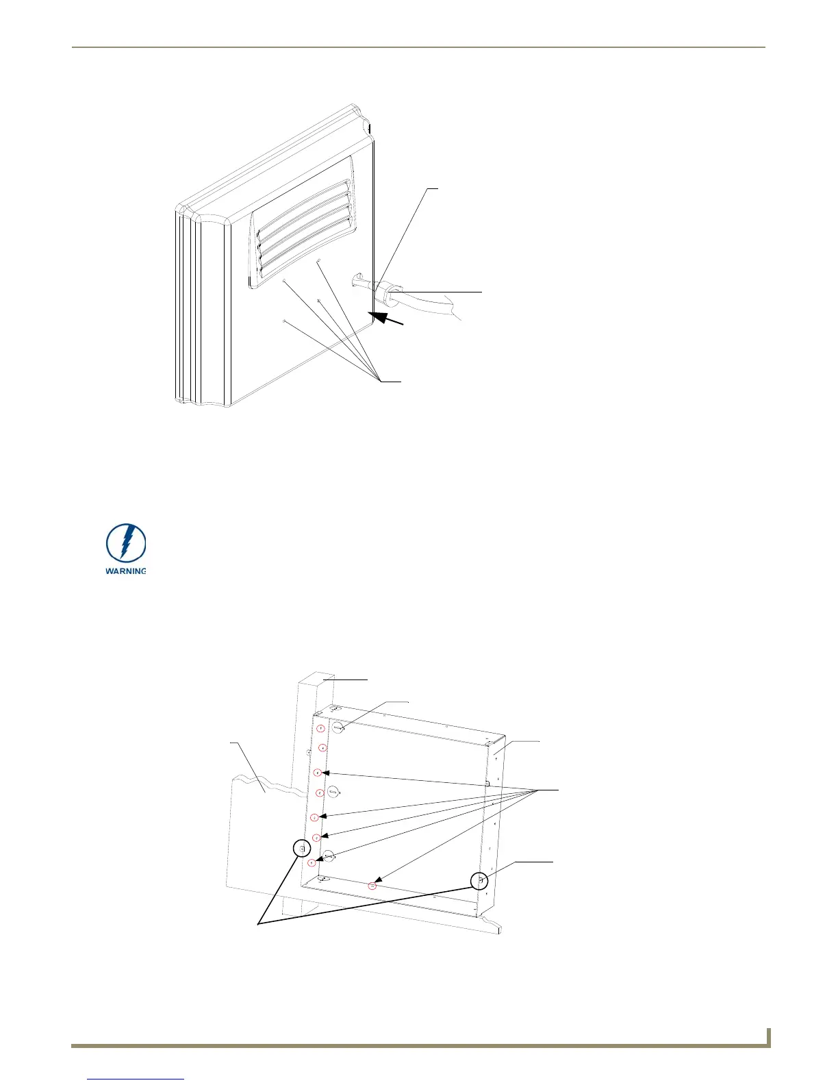
FIG. 36 Installation of grommet into the rear plastic enclosure
Rear plastic cover (rear view)
Rim of the strain relief grommet
should lie flush against enclosure
CLIP FACING UP
VESA mount connection location
(USE ONLY AMX PROVIDED #8-32 screws)
INSTALLER: LEAVE A GAP BETWEEN THE STUD AND CONDUIT BOX TO
ACCOMMODATE THE DRYWALL SHEETROCK. This gap allows the installation of
the drywall/sheetrock after the conduit box has been installed.
FIG. 37 Screw locations for conduit box attachment in a pre-wall installation
Drywall/
Stud
Knockouts should be located on the left-side of the
CB-TP Conduit Wallbox
conduit box, alongside the connectors
Stud fastening holes
Use the four #4-40
Mounting Screws to
secure the NXD to the
conduit box at these
sheetrock
Mounting tabs
for NXD panel should
be flush with the outside of the sheetrock
locations
 Loading...