Upgrading Modero Firmware
74
NXD/T-1200V Wall/Flush Mount Touch Panel
16. Click Ye s to interrupt the current communication from the Master and apply the new settings.
17. Click Reboot (from the Tools > Reboot the Master Controller dialog) and wait for the System Master to reboot. The
STATUS and OUTPUT LEDs should begin to alternately blink during the incorporation. Wait until the STATUS
LED is the only LED to blink.
18. Press Done once until the Master Reboot Status field reads *Reboot of System Complete*.
19. Click the OnLine Tree tab in the Workspace window to view the devices on the System.
The default System value is one (1).
20. Right-click the associated System number and select Refresh System. This establishes a new connection to the
specified System and populates the list with devices on that system. The communication method is then highlighted
in green on the bottom of the NetLinx Studio window.
Step 2: Prepare the panel for communication via an IP
1.
Press the blue Type field (from the Master Connection section) until the choice cycles to the word Ethernet.
2. Press the blue Mode field until the choice cycles to the word URL.
By selecting URL, the System Number field becomes read-only (grey) because the panel pulls this value
directly from the communicating target Master (virtual or not). A Virtual Master system value can be set
within the active AMX software applications such as: NetLinx Studio, TPD4, or IREdit.
3. Press the red Master IP/URL field to open a Keyboard and enter the NetLinx Master’s IP Address (obtained from
the Diagnostics - Networking Address dialog of the NetLinx Studio application).
4. Click Done to accept the new value and return to the System Configuration page.
5. Do not alter the Master Port Number value (this is the default value used by NetLinx).
6. Press the Back button to return to the Protected Setup page and press the on-screen Reboot button to restart the
panel and save any changes.
Step 3: Verify and Upgrade the panel firmware via an IP
1.
Click the OnLine Tree tab in the Workspace window to view the devices on the System. The default System value
is one.
2. Right-click the associated System number (from the Workspace window) and select Refresh System to detect of all
devices on the current system, establish a new connection to the Master, and refresh the System list with devices on
that system.
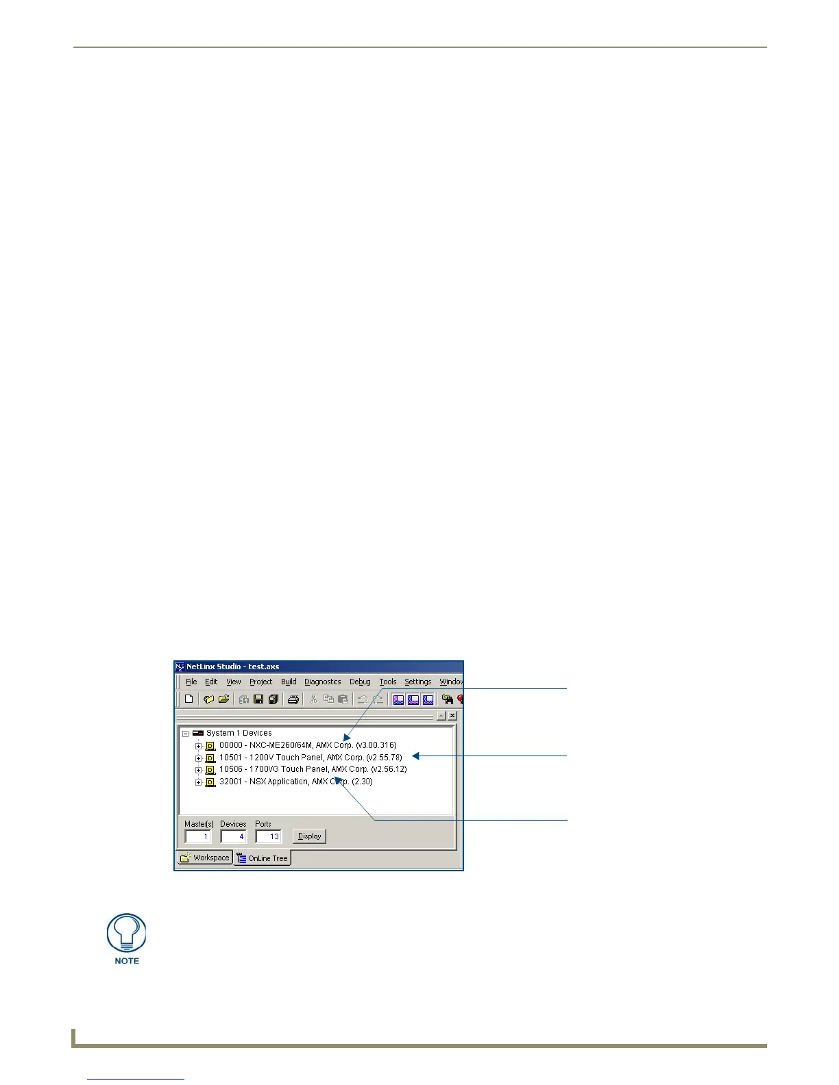
3. After the Communication Verification dialog window verifies active communication between the PC and the
Master, verify the panel appears in the OnLine Tree tab of the Workspace window (FIG. 76). The default Modero
panel value is 10001.
FIG. 76 NetLinx Workspace window (showing connected Modero panel)
Showing a Master
firmware version and
device number
Showing the current Modero
panel firmware version and
device number
Shows NetLinx Studio
version number
The panel firmware is shown on the right of the listed panel.
 Loading...