Configuring Communication
60
NXD/T-1200V Wall/Flush Mount Touch Panel
Step 3: Configuring the Ethernet Connection Type
Before beginning:
1. Verify the panel has been configured to communicate either through an Ethernet cable (connected from either the
panel to a valid Ethernet Hub) or to a wirelessly to the Wireless Access Point (WAP).
2. Verify that the NetLinx Master is receiving power and is communicating via an Ethernet connection with the PC
running NetLinx Studio.
3. Connect the terminal end of the 12 VDC-compliant power supply cable to the power connector on the rear/side of
the touch panel.
4. Verify the green Ethernet LED (from the rear Ethernet port on the Master) is illuminated (indicating a proper
connection).
5. Verify the yellow LED (from the rear Ethernet port on the Master) is blinking (indicating communication).
6. After the panel powers-up, press and hold the grey Front Setup Access button (for 3 seconds) to proceed to the
Setup page.
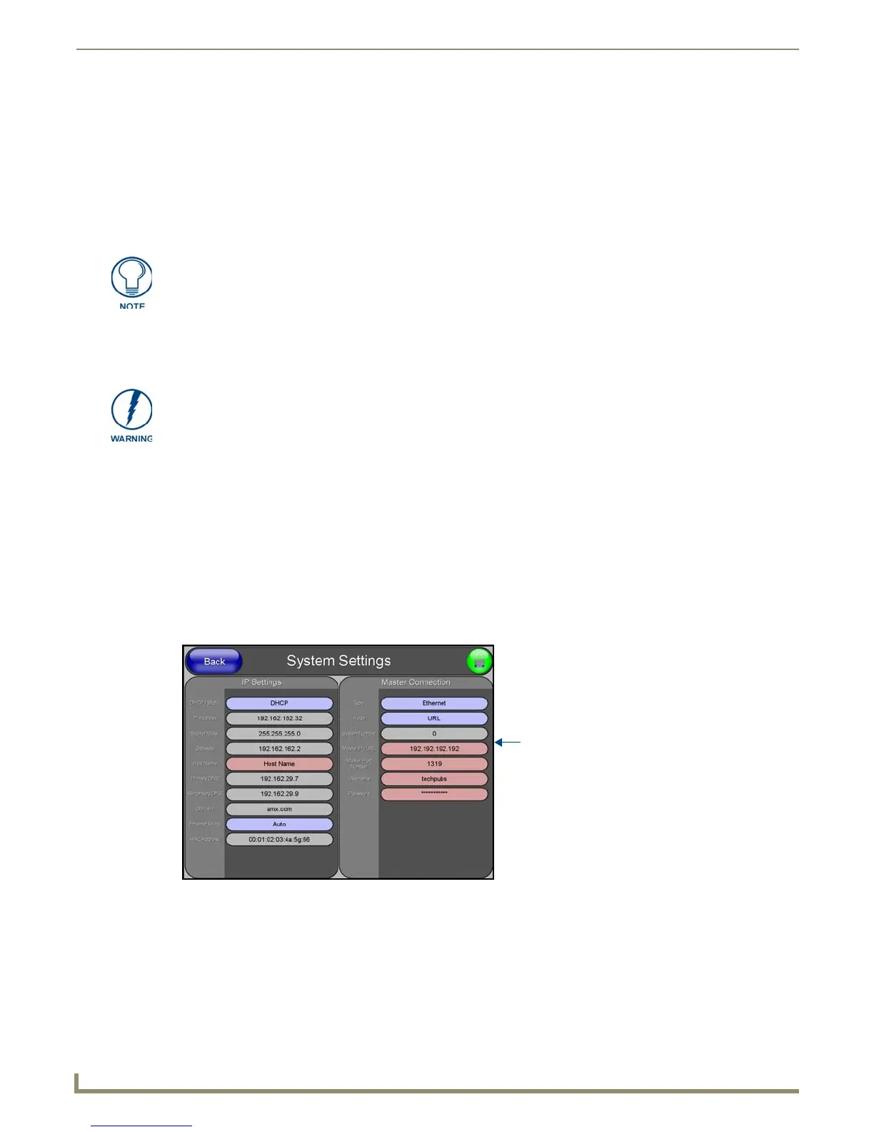
7. Select Protected Setup > System Settings (located on the lower-left) to open the System Settings page (FIG. 63).
• AUTO is used to instruct the Modero to search for a Master that uses the same System Number (assigned
within the Master Connection section) and resides on the same Subnet as itself. In this case, the Master has its
UDP feature enabled.
This UDP (User Datagram Protocol) is a protocol within the TCP/IP protocol suite that is used in place of TCP
when a reliable delivery is not required. This UDP enabling is done through a Telnet session on the Master. Refer
to the particular NetLinx Master manual for more detailed information.
When using Ethernet as your communication method, the NetLinx Master must first
be setup with either a Static IP or DHCP Address obtained from either NetLinx Studio
or your System Administrator.
Before commencing, verify you are using the latest NetLinx Master firmware.
FIG. 63 System Settings page
Obtained
from
NetLinx
Master
 Loading...