Configuring Communication
51
NXD/T-1200V Wall/Flush Mount Touch Panel
number used in step 7 for the VNM is entered into the Master Connection section of the System Settings page
and the panel is restarted.
The Connection status turns green after a few seconds to indicate an active USB connection to the PC (Virtual
Master). No Lock icon is displayed because this USB connection is not secured (requiring a username/
password).
If a few minutes have gone by and the System Settings icon still does not turn green, repeat the USB
connection and Virtual Master setup procedures (outlined in this section). Refreshing the System sends out a
request to the panel to respond and completes the communication (turning the System Connection icon
green).
Step 5: Confirm and View the current AMX USB device connections
Use the CC-USB Type-A to Mini-B 5-wire programming cable (FG10-5965) to provide communication between the
mini-USB Program port on the touch panel and the PC. This method of communication is used to transfer firmware KIT
files and TPD4 touch panel files.
1. Verify this direct USB connection (Type-A on the panel to mini-USB on the panel) is configured properly using the
steps outlined in the previous two sections.
2. With the panel already configured for USB communication and the Virtual Master setup within NetLinx Studio, its
now time to verify the panel is ready to receive files.
3. Click the OnLine Tree tab in the Workspace window to view the devices on the Virtual System.
The default System value is one.
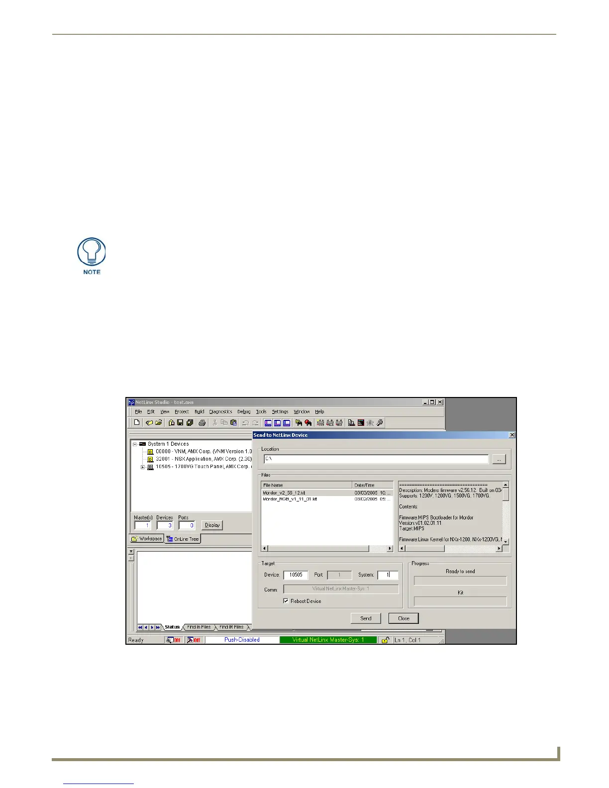
4. Right-click on the System entry (A in FIG. 57) and select Refresh System. This causes a refresh of all project
systems, establishes a new connection to the Virtual Master, and populates the System list with devices on your
particular system.
A mini-USB connection is only detected after it is installed onto an active panel.
Connection to a previously powered panel which then reboots, allows the PC to
detect the panel and assign an appropriate USB driver.
FIG. 57 Using USB for Virtual Master communication
 Loading...