Configuring Communication
49
NXD/T-1200V Wall/Flush Mount Touch Panel
The driver does not contain a Microsoft
®
digital signature and Windows
®
then informs you of such.
9. Click Ye s when told that a digital signature was not found. This action accepts the installation of the new USB
driver. The panel is now configured to communicate directly with the PC.
This process completes the association between driver and device.
Each time the same touch panel is connected to the computer the driver is automatically loaded (using
a unique name - example USB LAN LINK #1, #2).
Each time a different touch panel is connected to the computer, the previous procedures will need to be
repeated.
The previous version of the AMX USBLAN driver showed a USB connection icon in the system tray when a
panel was connected. The new version of the driver does not show an icon in the System Tray.
10. Navigate back to the System Settings page.
Step 3: Confirm and View the current AMX USB device connections
1.
Navigate to Start > Settings > Control Panel > and double-click the System icon to launch the System Properties
dialog.
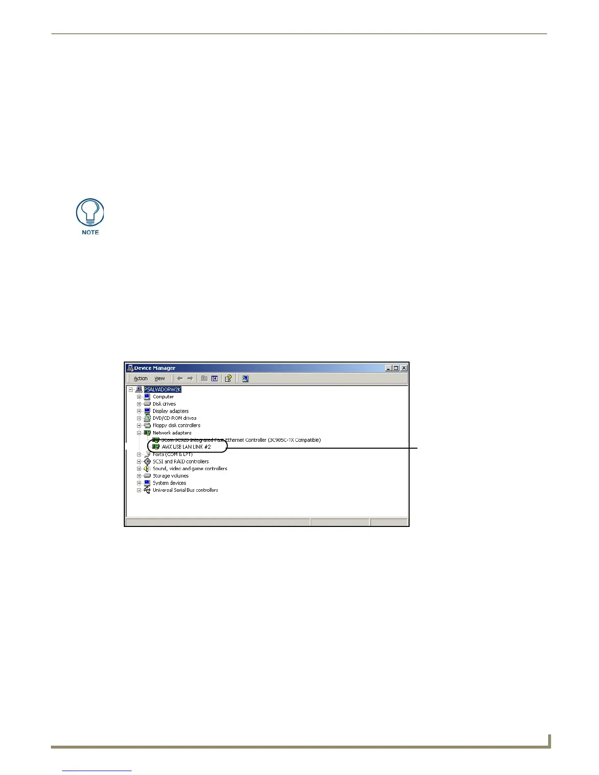
2. Select the Hardware tab and click on the Device Manager button to launch the Device Manager dialog.
Within the Device Manager dialog, the AMX USBLAN device appears under Network Adapters (FIG. 55)
and has a unique name such as AMX USB LAN LINK #2. The number changes depending on which
recognized panel is currently connected.
To remove the USB driver association from a previously connected touch panel, you must navigate back to the Device
Manager, right-click on the panel’s USB driver (example AMX USB LAN LINK #2) and select Uninstall from the
context menu and then OK.
Once the system completes the removal of the device, the Device Manager window will refresh, and the
device will no longer appear.
The next time this device is connected to the computer it will appear as a new hardware device and will need
to be associated again with the driver (refer to Step 2: Confirming the Installation of the USB Driver on the
PC section on page 47.
A Virtual NetLinx Master (VNM) is used when the target panel is not connected to a
physical NetLinx Master. In this situation, the PC takes on the functions of a Master
via a Virtual NetLinx Master. This connection is made by either using the PC’s
Ethernet Address (via TCP/IP using a known PC’s IP Address as the Master) or
using a direct mini-USB connection to communicate directly to the panel.
FIG. 55 Device Manager dialog showing USB device
USB connected touch
panel (showing the
recognized panel)
 Loading...