Installation Procedures: NXD-1200V Panels
34
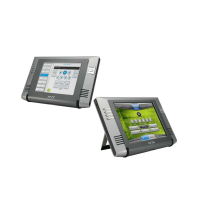
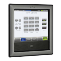
NXD/T-1200V Wall/Flush Mount Touch Panel
2. Remove any necessary wiring knockouts from the (optional) conduit box (C in FIG. 37) where the necessary cables
are threaded through for connection to the touch panel.
3. Thread the incoming RJ-45, Ethernet, and any other audio/video wiring through the knockouts. Refer to the Wiring
Guidelines for the 1200V Panels section on page 41 for pinout descriptions. Leave enough slack in the wiring to
accommodate any re-positioning of the panel.
4. Install the drywall/sheetrock before inserting the main NXD unit into the CB-TP12.
Installation of the NXD Touch Panel
The NXD panel can be installed either directly into the (optional) CB-TP12 or other solid surface environment using the
two different mounting options: drywall clips or solid surface screws. The following sections describe mounting the
touch panel directly into a pre-wall installed conduit box, a solid surface or drywall, and optional NXA-RK Rack Mount
Kit.
Installing the NXD panel within a Conduit Box
The conduit box must be mounted prior to continuing this section. Refer to the procedures in the Pre-wall Installation of
the Conduit Box section on page 33 for detailed pre-wall installation instructions. Verify that all necessary cables have
been threaded through the knockouts on the conduit box and the connections have been tested prior to installation of the
NXD panel.
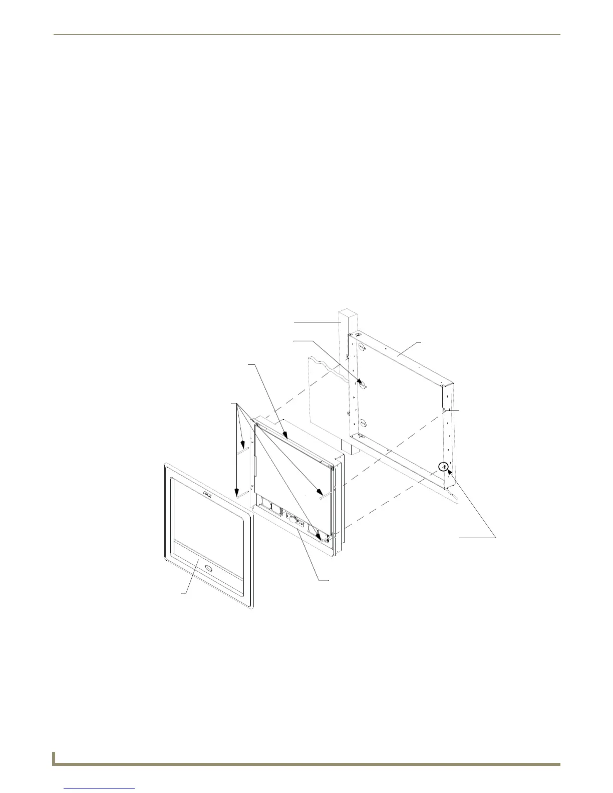
1. Remove the magnetic faceplate/bezel (A in FIG. 38) from the main NXD unit (B in FIG. 38) by gripping the
faceplate and pulling with gentle outward force.
2. Verify the incoming RJ-45, Ethernet, USB, and any other audio/video cables have been properly threaded through
the wiring knockouts (from their terminal locations) on the conduit box. Leave enough slack in the wiring to
accommodate any re-positioning of the panel.
3. Connect all data and power wiring connectors to their corresponding locations along the side of the (un-powered)
NXD touch panel.
Verify the terminal end of the power cable is not connected to a power supply before plugging in the 2-pin
power connector.
FIG. 38 Wall Mount panel installation configuration for pre-existing conduit/wallbox in a pre-wall construction
B - Main NXD unit consists of
C - Optional CB-TP
Install the four #4-40
screws into the places
indicated
Stud
the touch panel and backbox housing
conduit/wallbox
Cable
knockouts
Installed flush
against the
finished wall
Do not use these
tabs to mount
the conduit /wallbox
These are ONLY used to
secure the main unit to the CB
SURFACE
surface
A - Faceplate
(bezel)
Mounting Tab
 Loading...