Installation Procedures: NXD-1200V Panels
41
NXD/T-1200V Wall/Flush Mount Touch Panel
Wiring Guidelines for the 1200V Panels
These panels require the use of a 12 VDC-compliant power supply to provide power to the panel via the 2-pin 3.5 mm
mini-Phoenix PWR connector. Use the previously referenced power requirements information to determine the power
draw. The incoming PWR and GND wires from the power supply must be connected to the corresponding locations
within the PWR connector.
Preparing captive wires
You will need a wire stripper and flat-blade screwdriver to prepare and connect the captive wires.
1. Strip 0.25 inch (6.35 mm) of insulation off all wires.
2. Insert each wire into the appropriate opening on the connector (according to the wiring diagrams and connector
types described in this section).
3. Tighten the screws to secure the wire in the connector. Do not tighten the screws excessively; doing so may strip the
threads and damage the connector.
Wiring a power connection
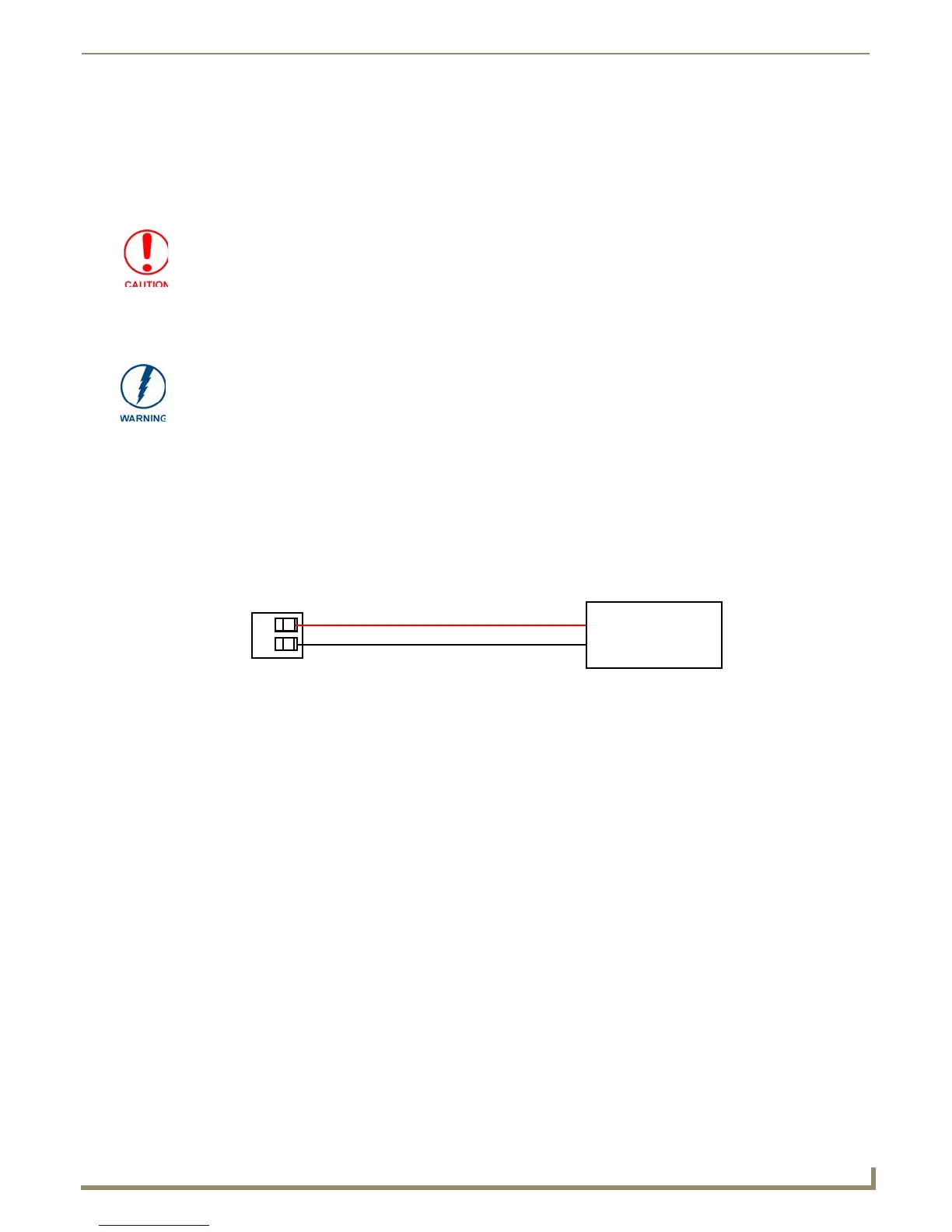
To use the 2-pin 3.5 mm mini-Phoenix connector with a 12 VDC-compliant power supply, the incoming PWR and GND
wires from the external source must be connected to their corresponding locations on the connector (FIG. 44).
1. Insert the PWR and GND wires on the terminal end of the 2-pin 3.5 mm mini-Phoenix cable.
Match the wiring locations of the +/- on both the power supply and the terminal connector.
2. Tighten the clamp to secure the two wires. Do not tighten the screws excessively; doing so may strip the threads and
damage the connector.
3. Verify the connection of the 2-pin 3.5 mm mini-Phoenix to the power supply.
These units should only have one source of incoming power. Using more than one
source of power to the touch panel can result in damage to the internal components
and a possible burn out.
Apply power to the panels only after installation is complete.
Never pre-tin wires for compression-type connections.
FIG. 44 NetLinx power connector wiring diagram
PWR +
GND -
To the Touch Panel
Power Supply
 Loading...