AD9361 Reference Manual UG-570
| Page 43 of 128
STATE 0: RESET
The AGC remains in this state when the AD9361 is not in the Rx
state. The AGC performs no actions while in this state.
STATE 1: PEAK OVERLOAD DETECT
When the AD9361 enters the Rx state, the AGC first waits for a
time in microseconds set by the AGC attack delay register. This
delay allows the receive path to settle before the AGC begins
determining the optimum gain index.
After this delay, the AGC enters State 1, where it detects peak
overloads (LMT and ADC) and adjusts the gain. The digital
saturation detector is also enabled, but in State 1 the signal may
not have enough time to reach the detector. Each time the gain
changes, the AD9361 holds the peak detectors in a reset state
until the Peak Overload Wait Time counter expires. If no peak
overloads are detected for the Energy Detect Count, then the
AGC can proceed to State 2. The Energy Detect Count is clocked
at the ClkRF rate (the clock used at the input to the Rx FIR filter).
The overloads affect the gain index in different ways for different
gain table types as shown in the Table 20 and Table 21. In full gain
table mode, the AD9361 uses different step sizes (changes in gain
index) for differing extremes of overload. Table 20 shows where
the step sizes are stored for the fast attack AGC in full table mode.
The Case #1 step size is typically larger than Case #2 which itself
is typically larger than Case #3.
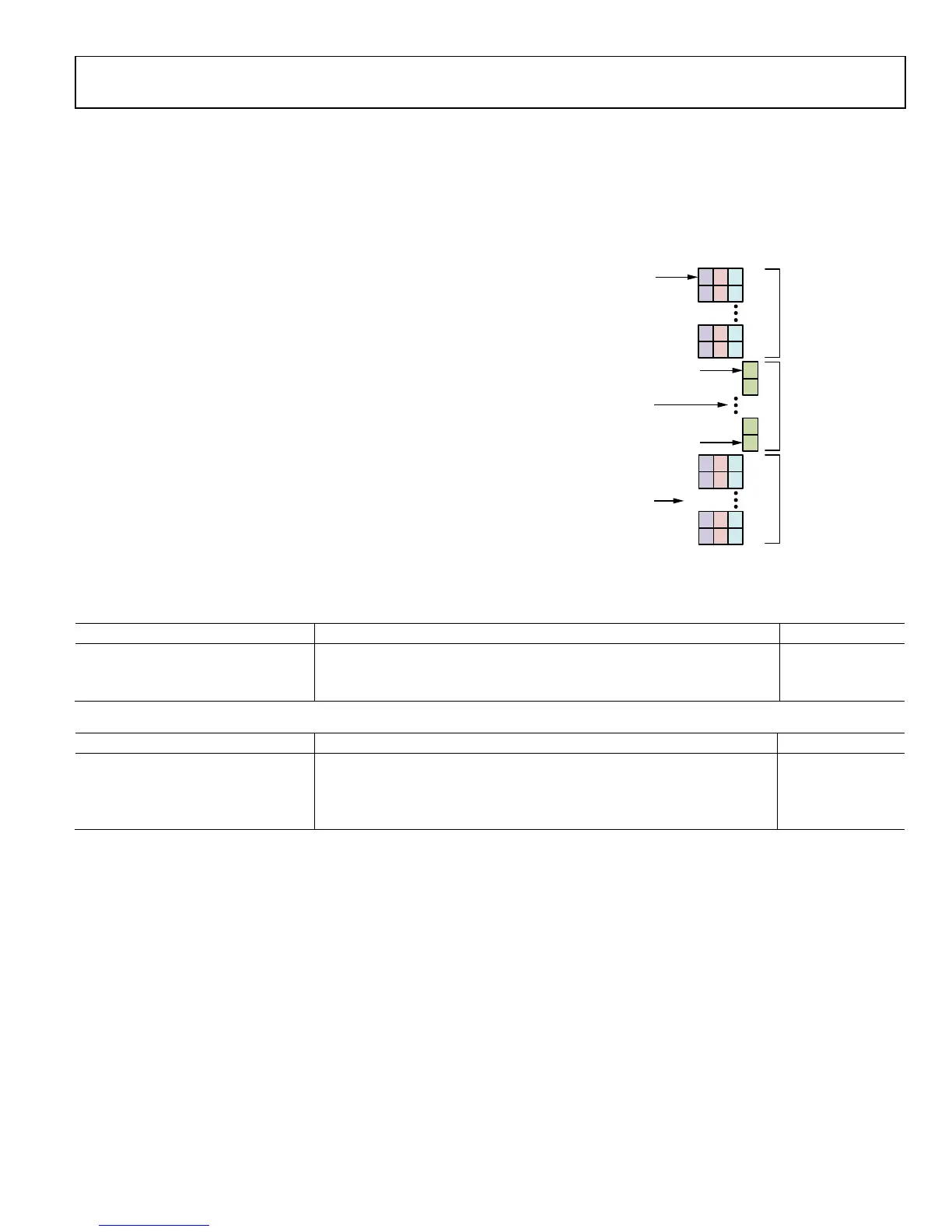
Table 21 shows the effects of various overloads when using a split
table. Figure 26 shows the split table architecture. Note that the
gain first decreases from the LMT table regardless of where the
overload occurs. When the gain index reaches the LMT index
limit, the gain decreases where the overload occurs.
Fig
ure 26. Fast AGC Split Gain Table Architecture
Ta
ble 20. Fast Attack AGC Peak Overload Step Sizes for Full Gain Table
Reduce Gain by this many Indices (Step Size)
Large ADC Λ (Large LMT V Digital Sat) Decrement Step Size for Full Table Case #1 0x106[D3:D0]
Large ADC V Large LMT V Digital Sat Fast Attack Only. Decrement Step Size for Full Table Case #2 0x106[D6:D4]
Small ADC Dec Step Size for Full Table Case #3 0x103[D4:D2]
Table 21. Fast Attack AGC Peak Overload Step Sizes for Split Gain Table
Overload Type Gain Index Position Change Gain In
Large LMT N/A LMT Table
Large or Small ADC LMT Index is in Upper LMT Table (Index > Initial LMT Gain Limit) LMT Table
Large or Small ADC LMT Index is in Lower LMT Table (Index ≤ Initial LMT Gain Limit) LPF Table
Digital Saturation N/A Digital Table
INDEX 0
INDEX 0
INDEX 24
LMT INDEX LIMIT + 1
LMT
UPPER
TABLE
LMT
LOWER
TABLE
LPF
GAIN
LMT INDEX LIMIT
(0x11A)
LMT MAX INDEX
(0x0FD)
LMT INDEX
(0x10A AND 0x10C)
LPF INDEX
(0x10B AND 0x10D)
11668-027

 Loading...


