AD9361 Reference Manual UG-570
| Page 57 of 128
INPUT MATCHING/ATTENUATION NETWORK
Tx_MON inputs require a matching/attenuation network to
provide matching to the driving source (typically a 50 Ω coupler
output) and to scale the input signal. Place matching
components, R1 to R3 and C1, as close as possible to the
AD9361. Tx_MON inputs are DC biased and the C1 capacitor
is an ac-coupling capacitor used to ac couple Tx_MON input.
R2 is a damping resistor to minimize series resonance
comprised of on-chip inductance and capacitance. The best way
to determine the optimum value for R2 is to empirically tune it
for desired TPM frequency response. Use proper transmission
line design techniques to design the signal path (TL1) from the
transmitter output coupler to the input of TPM. The higher the
frequency of operation the more critical this path becomes in
terms of loss and signal reflections.
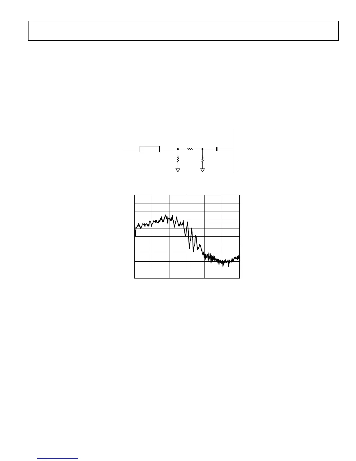
Figure 30 shows a measured TPM frequency response using the
matching circuit and component values in Figure 29. The
frequency response was optimized for 2.3 GHz frequency of
operation.
Figure 29. TPM Matching/Attenuation Input Network
Figure 30. TPM Frequency Response
R3R1 DNI
49.9Ω
R2
TX_MON
10Ω 100pF
Z
O
= 50Ω
C1TL1TX MONITOR INPUT
(FROM COUPLER AFTER PA)
11668-030
–5
50 6050
GAIN (dB)
FREQUENCY (MHz)
11668-130
50504050305020501050
–6
–7
–8
–9
–10
–11
–12
–13
–14
–15

 Loading...


