AD9361 Reference Manual UG-570
| Page 59 of 128
TPM DYNAMIC RANGE
TPM dynamic range can be maximized on the top end by
minimizing total TPM gain, that is, Tx Mon gain = 0 dB and
G
BBF
= 0 dB. The upper range of the input signal is +4 dBm in
that case (the upper range of the input signal can be increased
to 9 dBm by forcing TIA feedback resistor value to 1.75 kΩ by
setting Bits D6 and D7 in Register 0x1DC and Bits D0 and D2
in Register 0x1DB). Maximizing total TPM gain, that is, Tx
Mon Gain = 9.5 dB and G
BBF
= 30 dB minimizes the total input
referred noise thereby increasing the lower range of the input
signal to −78.9 dBm. The resulting total dynamic range can be
as high as 82.8 dB by following the previously described gain
control and making the gain switch threshold occur at
−35.2 dBm input signal level.
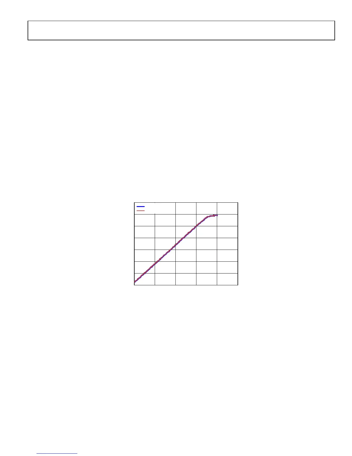
Figure 32 shows a linear dynamic range of about 70 dB that can
be achieved for three different input signal ranges with Tx Mon
Gain set to 0 dB, 6 dB or 9.5 dB and G
BBF
= 0 dB (see Table 41
for the input signal level ranges that correspond with these
three different gain settings. This approach uses the same Tx
Mon Gain and G
BBF
gain settings across the whole attenuation
range.
EXAMPLE OF TxMON CONFIGURATION AND
MEASUREMENT OF TPM TRANSFER FUNCTION
The following example is based on measured results using a
direct connection from the Tx1 output to the Tx Mon input on
an evaluation board. The goal of the example is to show how to
use the AD9361 TPM and an advanced application to extend
the dynamic range of TPM. The frequency of operation was
2300 MHz and transmitted signal was a 1 MHz CW signal.
TPM can be enabled in multi-chip sync and Tx Mon Control
Register 0x001 using Bits D5 and D6, and in TPM Mode Enable
Register 0x06E Bits D5 and D7. The preferred way to enable
TPM is to set Bits D7 and D5 in Register 0x06E. The user also
needs to clear Bits D2 and D3 in Analog Power Down Override
Register 0x057 because TPM is powered down by default.
To maximize SNR, the Tx Mon Track bit should be set in
0x067[D5], which minimizes DC offset in the Tx monitor
signal path.
3
Figure 32. TPM Frequency Response
350
0
50
100
150
200
250
300
0 10080604020
RSSI CODE
TX ATTENUATION (dB)
FREE RUNNING
ONE SHOT
11668-033

 Loading...


