AD9361 Reference Manual UG-570
| Page 89 of 128
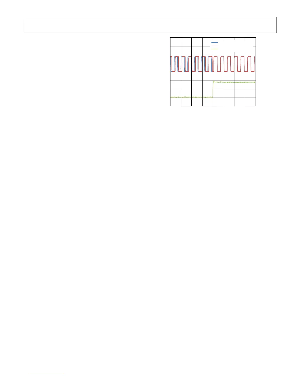
SYNCHRONIZATION VERIFICATION
Data synchronization can be verified by observing the
DATA_CLK signal of each chip simultaneously using an
oscilloscope. The waveforms will overlap after successfully
completing the sync procedure. Similarly, the CLK_OUT pin on
each device (when enabled) can be monitored to determine if
the ADC clocks are synchronized. Figure 62 illustrates the
DATA_CLK signals of two devices before and after the second
SYNC_IN pulse occurs. Note that the SYNC_IN pulse is much
longer in duration than the DATA_CLK signals in this example.
As long as the setup and hold times meet the requirements
listed in Figure 60 and Figure 61, this is an acceptable
combination because the SYNC_IN input is edge detected by
the REF_CLK reference.
Fig
ure 62. Clock Signals of AD9361 IC1 and IC2 Before and After Second
SYNC_IN Pulse (Initial Phase Random)
SYNC_IN INPUT PULSE
DATA_CLK BOARD 2
DATA_CLK BOARD 1
11668-063

 Loading...


