AD9361 Reference Manual UG-570
| Page 35 of 128
GAIN CONTROL
OVERVIEW
The AD9361 transceiver has several gain control modes that
enable its use in a variety of applications. Fully automatic gain
control (AGC) modes are available that address time division
duplex (TDD) as well as frequency division duplex (FDD)
scenarios. In addition, the AD9361 has manual gain control
(MGC) options that allow the BBP to control the gain of the
receiver. The ad9361_set_rx_gain_control_mode function
configures all of the gain control modes.
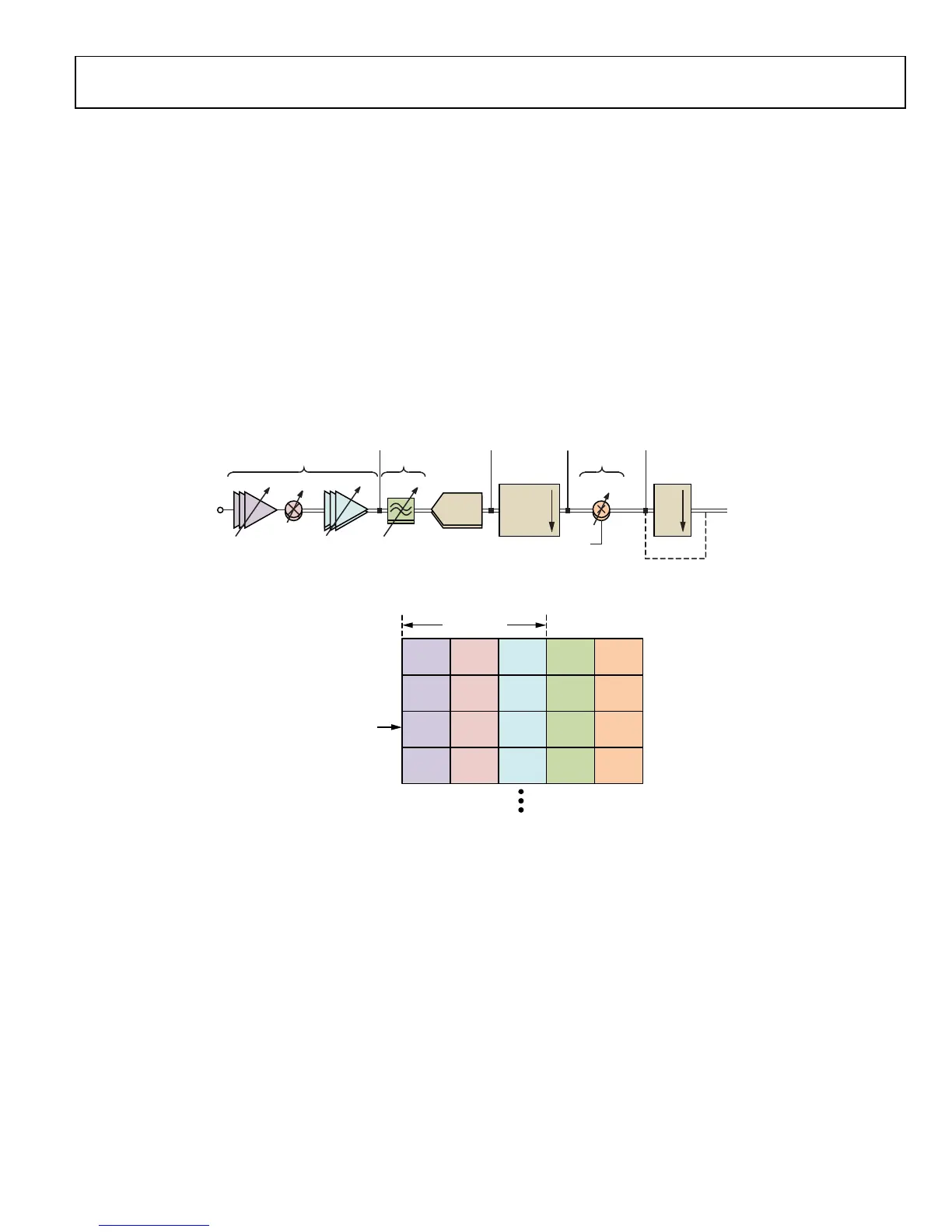
The AD9361 receive signal path can be broken up into several
blocks as shown in Figure 18. The gain of almost all of the
blocks is variable as shown by the arrows through the shapes in
Figure 18.
Each receiver has its own gain table that maps a gain control
word to each of the variable gain blocks in Figure 19. A pointer
to the table determines the control word values sent to each
block as shown in Figure 19. Whether automatic gain control
(AGC) or manual gain control (MGC) is used, the pointer
moves up and down the table, which changes the gain in one or
more of the blocks shown in Figure 18.
The ADC maximum input (0 dBFS) is 0.625 V peak. However,
to avoid compression the maximum recommend peak input
level to the ADC is 0.5 V peak, which is 1.9 dB lower than full
scale.
Figure 18. AD9361
Receive Signal Path
Figure 19. AD9361
Gain Table Mapping
ADC
RX
INPU
TO INPUT/
OUTPUT
PORT
LMT LPF
TRANS-Z
AMP (TIA)
DIGITAL
MILTIPLICAND
HALF-
BAND
FILTERS
RX
FIR
MIXERLNA LOW PASS
FILTER
DIGITAL
LMT PEAK
OVERLOAD
DETECTOR
DC PEAK
OVERLOAD
DETECTOR
LOW AVERAGE
POWER
DETECTOR
DIGITAL SAT
PEAK
DETECTOR
BYPASS
11668-019
GAIN INDEX
(POINTER)
LNA
GAIN
MIXER
GAIN
TIA
GAIN
LPF
GAIN
DIGITAL
GAIN
LMT GAIN
11668-020

 Loading...


