UG-570 AD9361 Reference Manual
| Page 60 of 128
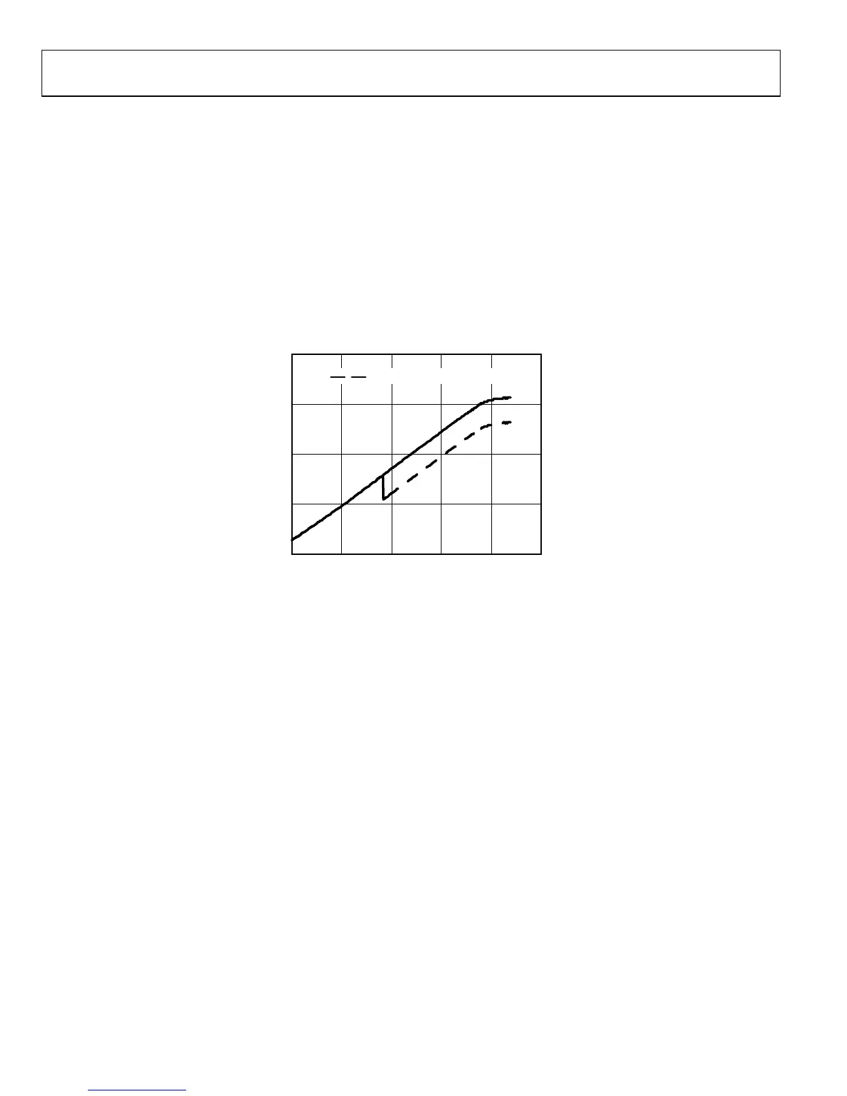
The resulting measured TPM transfer characteristics are shown
in Figure 33. The dashed line is uncompensated for Tx Mon
TIA gain change at the threshold and it shows a transition at
37 dB Tx attenuation (this corresponds to a threshold setting of
0x94 in Register 0x078). Below the threshold Tx Mon gain is
0 dB and G
BBF
is 0 dB. Above the threshold Tx Mon gain is
9.5 dB and G
BBF
is 0 dB. The compensated characteristic (solid
line in Figure 33) is a gain compensated version of the dashed
line. The resulting linear dynamic range is 76 dB, which is about
10 dB greater than the 66 dB dynamic range achievable with a
single gain setting.
As Figure 33 shows, the TPM TIA gain is not compensated by
the Tx RSSI algorithm. The 9.5 dB compensation that results in
the solid line would occur in the baseband processor.
TPM TEST MODE
It is possible to output TPM I/Q data at the Rx data port
in TDD mode in Tx state. This may be useful in some
applications.
The Enable Rx Data Port bit for calibration (Register 0x014 Bit
D7) needs to be set and TPM enable in Register 0x06E to be in
this test mode.
Figure 33. Tx Monitor TxRSSI vs. Tx Attenuation
400
300
200
100
0
0204060 100
TxRSSI
TX ATTENUATION (dB)
80
UNCOMPENSATED FOR TX MON GAIN
11668-034

 Loading...


