1-3 Replaceable Parts General Information
1-4 PN: 10580-00177 Rev. D MS2721B MM
1-3 Replaceable Parts
Table 1-3 contains a list of parts that can be replaced in the Model MS2721B Spectrum Master.
Coupler Frequency: 881.5 MHz
Coupling Factor: 30 dB
Midwest Microwave Model
CPW-5140-30-NNN-05 or
CPW-5141-30-NNN-05
Alternative: Anritsu part number
1091-307 [Two SMA(m)-to-N(f) adapters
required.]
Circulator Frequency Range:
800 to 1000 MHz
Isolation: 20 dB min.
Meca Electronics, Inc. part number
CN-0.900
Alternative: Anritsu part number 1000-50
[Two SMA(m)-to-N(f) adapter and one
SMA(m) to SMA(m) Adapter required.]
RF Coaxial Cable Frequency: DC to 18 GHz
N(m)-N(m), 50 Ohm
Anritsu Model 15NN50-1.5B (Qty 3)
RF Coaxial Cable Frequency: DC to 6 GHz
N(m)-N(m), 50 Ohm
Anritsu Model 15NN50-1.5C (Qty 3)
GPS Antenna Anritsu 2000-1410
Coaxial Cable BNC(m)-BNC(m), 50 Ohm Any (Qty 2), or
Anritsu part number 2000-1627-R
a.Note that MG3692A models require Option 15 to achieve power of +13 dBm. MG3692B models do not require Option 15 to
achieve +13 dBm power.
b.Note that the tests in this manual require that the MG3700A has several factory custom test pattern files installed into its
memory.
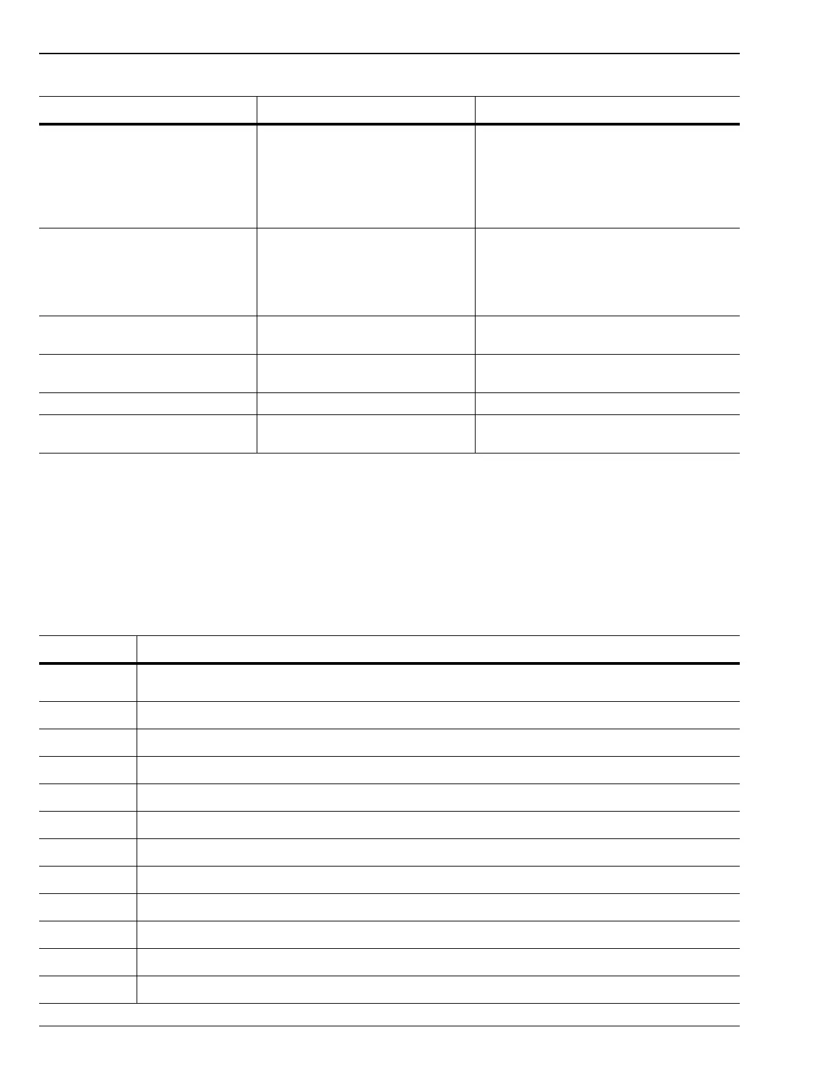
Table 1-3. Replaceable Parts in the Model MS2721B Spectrum Master
Part Number Description
ND67985
MS2721B Main/Spec Analyzer PCB Assembly, with Option 9 and Option 31 or Support Opt.09/31.
For units with S/N < 1003000
ND71298 MS2721B Main/SPA Assembly, Support Opt.09/30/31/32/64/78. For S/N < 1003000
ND71306 MS2721B Main/SPA Assembly, Support Opt.9/31. For units with S/N > 1002999
ND71308 MS2721B Main/SPA Assembly, Support Opt.09/30/31/32/64/78. For units with S/N > 1002999
ND68502 MS2721B Main/SPA/BER Assembly, Support Opt.09/31/57. For units with S/N < 1003000
ND71307 MS2721B Main/SPA/BER Assembly, Support Opt.09/31/57. For units with S/N > 1002999
ND67553 Tracking Generator PCB (Option 20)
ND66821 MS2721B Demodulation PCB (Option 9)
3-790-661 Gasket material for case edge
3-15-118 LCD Display
61368 Clear Plastic LCD Protector
3-66549-3 LCD Backlight Inverter PCB
Table 1-2. Test Equipment Required for Verifying Functions of Installed Options
Instrument Critical Specification Recommended Manufacturer/Model

 Loading...


