4-5 Removal of the Spectrum Analyzer PCB Remove and Replace
4-6 PN: 10580-00177 Rev. D MS2721B MM
4-5 Removal of the Spectrum Analyzer PCB
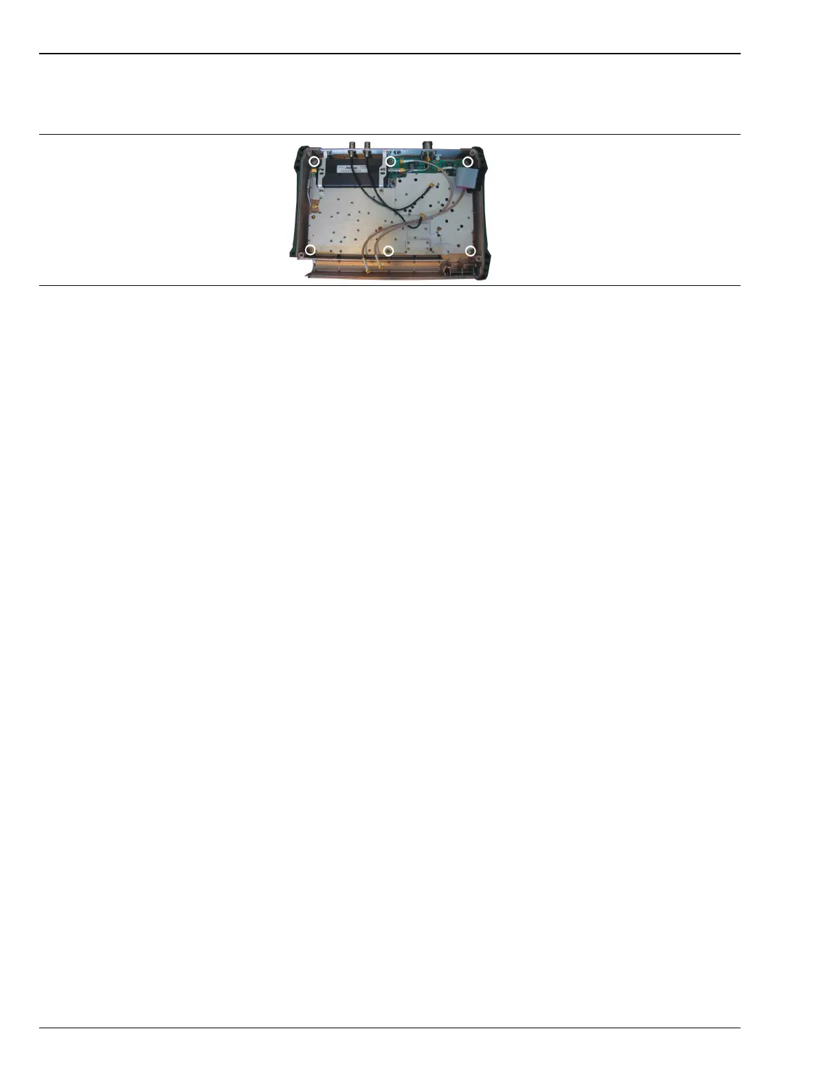
Figure 4-7 shows the spectrum analyzer PCB in the case.
Remove the six larger screws around the edge of the PCB (circled in the figure) to release the board from the
case. Do not remove or adjust any smaller screws that pass through the RF shields. Do not loosen or remove
the step attenuator or any cables.
4-6 Removal and Replacement of the Tracking Generator (Option 20)
If Option 20 is installed, then the tracking generator module is mounted over the Spectrum Analyzer PCB. To
remove the tracking generator module:
1. Remove the semi-rigid and flexible cables from the tracking generator module.
2. Remove the 8 screws that secure the tracking generator module to the SPA PCB. The screws are labeled
with the letters A, B, and C engraved in the cover (four labeled A, three labeled B, and one labeled C).
3. Two RF connectors (SMP type) are located under the tracking generator module. They connect it to the
SPA PCB. Carefully lift the tracking generator module straight up off of the SPA PCB.
The RF connectors may be removed by using padded-jaw or other pliers, but can be damaged by this
process. Replacement RF connectors are included in the tracking generator replacement kit, but if the
spectrum analyzer board is to be returned, replacement connectors are not included. Replacement RF
connectors can be ordered. (Refer to “Replaceable Parts” on page 1-4).
The tracking generator exchange kit does not include the semi-rigid RF cable that is attached to the
tracking generator module nor the connector panel Type N connector. Retain these items for reuse with
the replacement tracking generator.
4. Installation of the replacement tracking generator is the opposite of removal. No recalibration is
required.
4-7 Removal of the Main PCB/LCD Assembly
1. Push the external CF card ejector button to the IN position.
2. Unplug the cables to the fan, battery pack connector, and knob from the Main PCB.
3. Remove the 8 screws around the edge of the board to release the PCB/LCD assembly from the case.
4. Carefully lift the Main PCB/LCD assembly out of the case.
Figure 4-7. Spectrum Analyzer PCB and Retaining Screws

 Loading...


