Performance Verification 1 2-2 Spectrum Analyzer Function Verification
MS2721B MM PN: 10580-00177 Rev. D 2-29
9 kHz to 100 kHz Amplitude Accuracy Verification Setup:
2. Set the MG3692x frequency to 100 kHz CW and the output power to approximately –5 dBm.
3. Adjust the MG3692x output power so that Power Sensor B reads –20 dBm ± 0.1 dB on the power meter.
4. Remove Power Sensor B from the splitter and Attenuator, and attach the N female end of the T3449 test
fixture to the splitter (via the Attenuator) through an N male-to-N male adapter. Connect the BNC
output of the T3449 to the AC voltmeter voltage input via a BNC male to BNC male coaxial cable and
BNC female to banana plug adapter. Ensure that the voltmeter (DVM) is set to read AC volts.
5. Set the AC voltmeter to measure AC volt rms. The measured voltage should read 23.315 mV ± 0.5 mV.
Record the actual measured value to the Vm1 box in Table A-33, “Measured VM1, –20 dBm Reference
voltage at 100 kHz (23.315 mV ± 0.5 mV)” on page A-12.
6. While keeping the MG3692x output power unchanged, set the frequency to 95 kHz and record the
measured voltage into the Vm2 column in Table A-34, “Characterization Chart for 9 kHz to 100 kHz
Amplitude Accuracy Verification” on page A-12.
7. Convert the measured voltage to power in dBm by using the following formula:
P
in
= 20*Log
10
(Vm2/Vm1) + correction factor
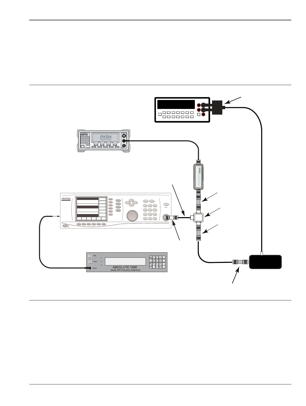
Figure 2-12. 9 kHz to 100 kHz Amplitude Accuracy Verification Component Characterization
34401A
6½ Digit Multimeter
Sensor A
Power Splitter
ML2438A Power Meter
MG369XA Source
10 MHz Reference
to rear panel
connector
Attenuator
10 dB
Attenuator
10 dB
DVM
T3449
Adapter
BNC - Banana
Adapter
N-Male to N-Male
15NNF50-1.5B
Adapter

 Loading...


