Performance Verification 2 3-7 GSM/GPRS/EDGE Signal Analyzer (Options 40 and 41) Verification
MS2721B MM PN: 10580-00177 Rev. D 3-35
Set up Procedure:
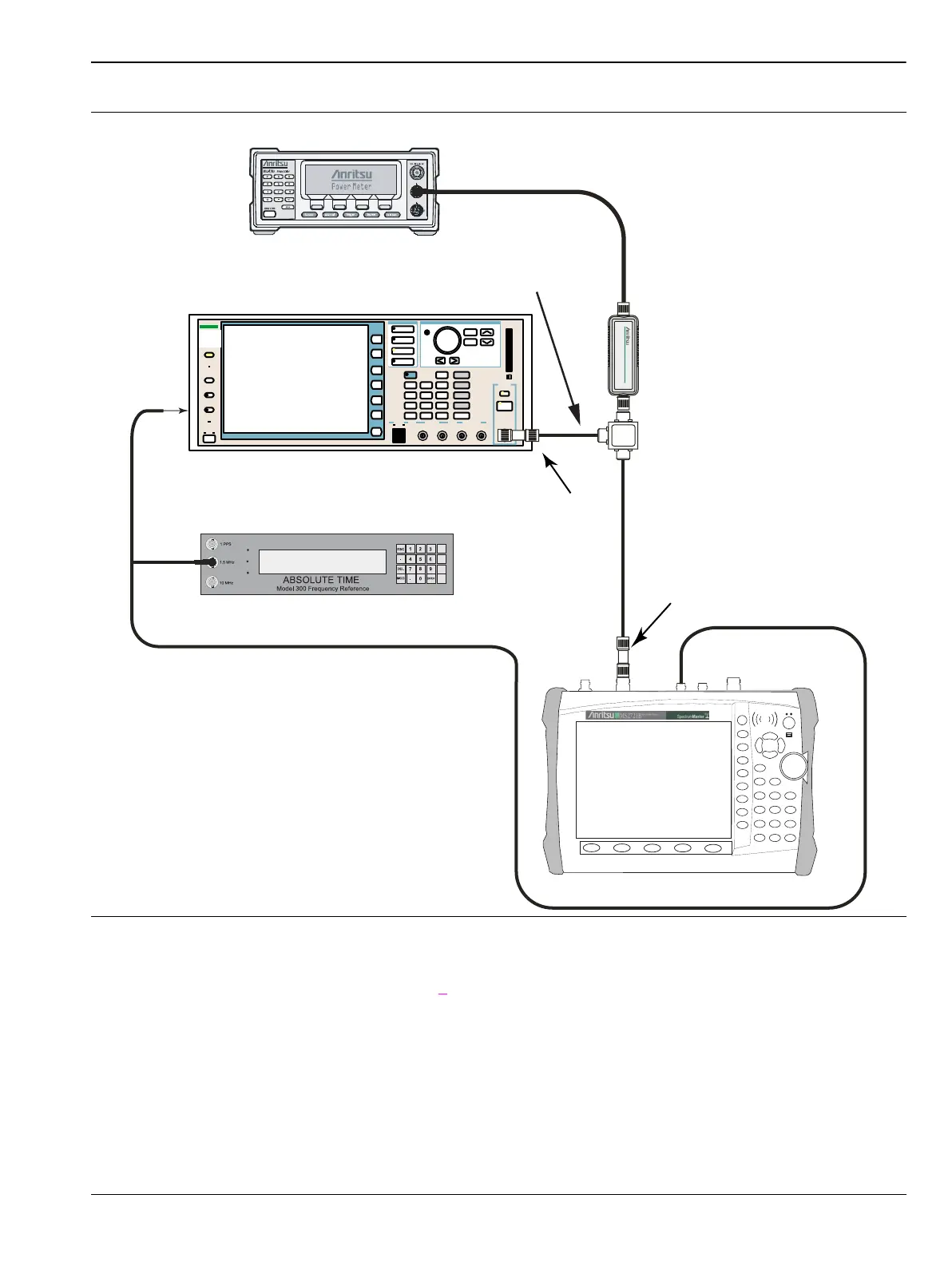
1. Connect the equipment as shown in Figur
e 7.
2. Calibrate the power sensor prior to connecting to the power splitter.
3. On the power meter, press the Sensor key, the Cal Factor soft key, and then the Freq soft key. Use the
keypad to enter 850 MHz as the input signal frequency, which sets the power meter to the proper power
sensor calibration factor. Press the System key to display the power reading.
4. Set the MS2721B mode to GSM/GPRS/EDGE Signal Analyzer. Preset the instrument.
Figure 3-12. GSM/GPRS/EDGE Test Setup
Function
Ethernet Control Input Modulation Input
Cursor/Edit
RF Output
3
MG3700
Vector Signal
Generator
250kHz-6GHz
MG3700A
ML2438A Power Meter
10 MHz Reference
To Ext Ref In
(to back panel)
Power
Splitter 1870A
Adapter
N(m) to N(m)
MS2721B
Power Sensor
MA2482D
Adapter
15NNF50-1.5B

 Loading...


