ASE2000 V2 Communication Test Set User Manual 105
20.3. BCOM-USB Components
When provided as an “Upgrade Kit” to an existing ASE2000 Test Set kit with a PCMCIA card,
parallel port dongle, or USB dongle, the above components plus documentation and software
installation CD will be provided. The RS-232 Monitor Cable, DB-9 to DB-25 adaptors, NULL
modem adaptor, and gender changer from the original test set kit will be retained and used with
the BCOM-USB. The test set enabling device, BCOM-PCMCIA card or dongle, must be returned
as part of the Upgrade Procedure.
When provided with a new, complete ASE2000 Communication Test Set, the BCOM-USB
components together with the other standard test set kit cables and adaptors will be provided.
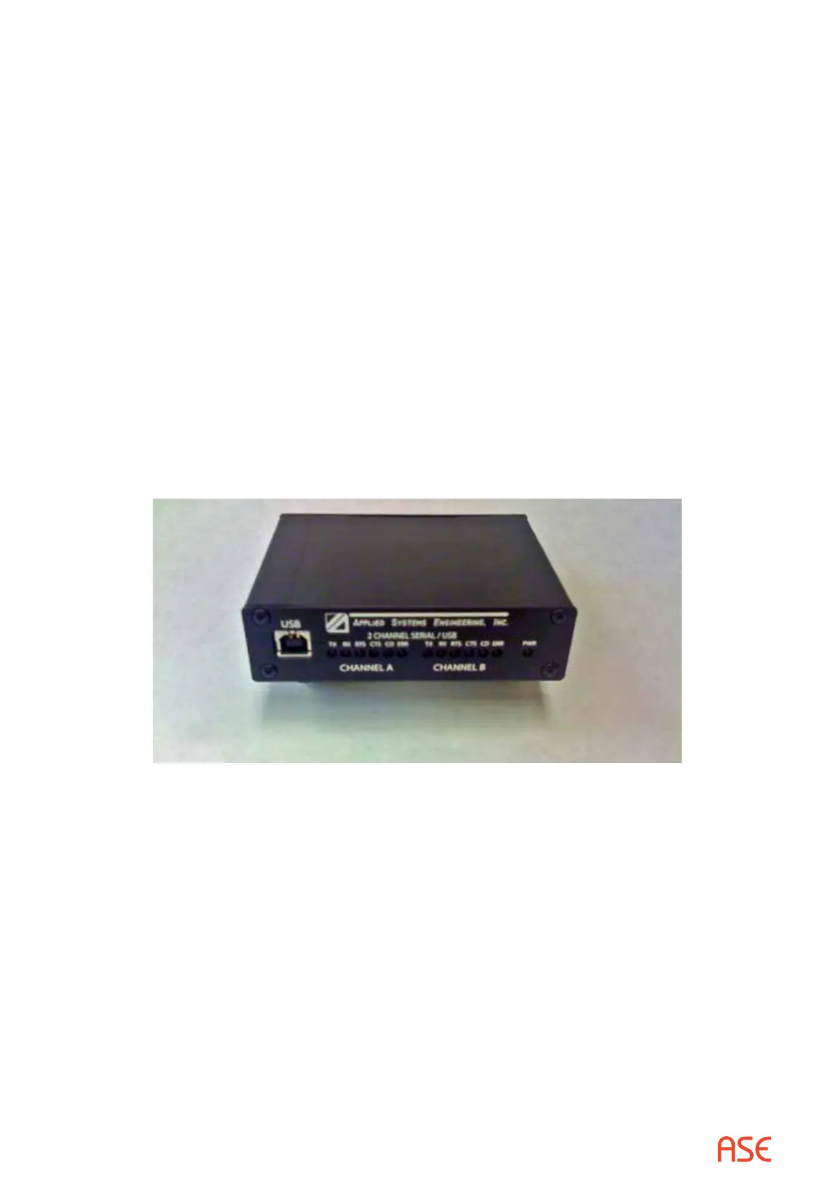
The front of the BCOM-USB device has a USB connector for connection to a PC and LED
indicators for serial communication activity indications. Each channel has:
TX – Transmit Data
RX – Receive Data
RTS – Request To Send
CTS – Clear To Send
CD – Data Carrier Detect
ERR – Error Indication
Front View
The back of the BCOM-USB device has two DB-9 Male connectors and a Modem Power
connector. The +5VDC Modem Power connector (MDM PWR OUT) is only for powering the
ASE 2-channel Bell-202 Test Set Modem from the BCOM-USB device. IT MUST NOT BE USED
FOR ANY OTHER PURPOSE!
 Loading...