ASE2000 V2 Communication Test Set User Manual 214
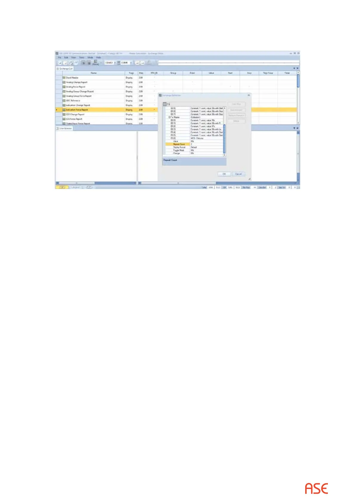
From the Exchange view, right-click on the line containing the Indication Force Report exchange
and select Edit Exchange Denition.
Under the “To Master” section, expand the element “MCD: unknown quantity of blocks”, set
“Repeat Count” to 2 (8 Indication points per count), then OK.
30.1.2. Telegyr 8979 – Set RTU ID and Group
The RTU ID can be set for all exchanges from the Tools>Properties>Protocol tab display or
individually on the Exchange List view.
30.1.3. Telegyr 8979 – Exchange Mode Line Monitor
No additional setup is required. If cabling is correct Line Monitoring can be started by selecting
the Start button.
30.1.4. Telegyr 8979 – Exchange Mode Master Simulation
If the Communication Properties, Exchange Denition, and RTU ID have been congured, set
the Start and Stop point numbers for the Analog Force Report and Indication Force Report on the
Exchange Properties display or on the Exchange List display. Bring up the associated Exchange
Properties display by double-clicking on the exchange name on the Exchange List display. In the
following example, Start/Stop have been congured for 8 analog and 16 MCD points.
 Loading...