ASE2000 V2 Communication Test Set User Manual 96
17. RS-232 Cable And Adapter Pin-Out
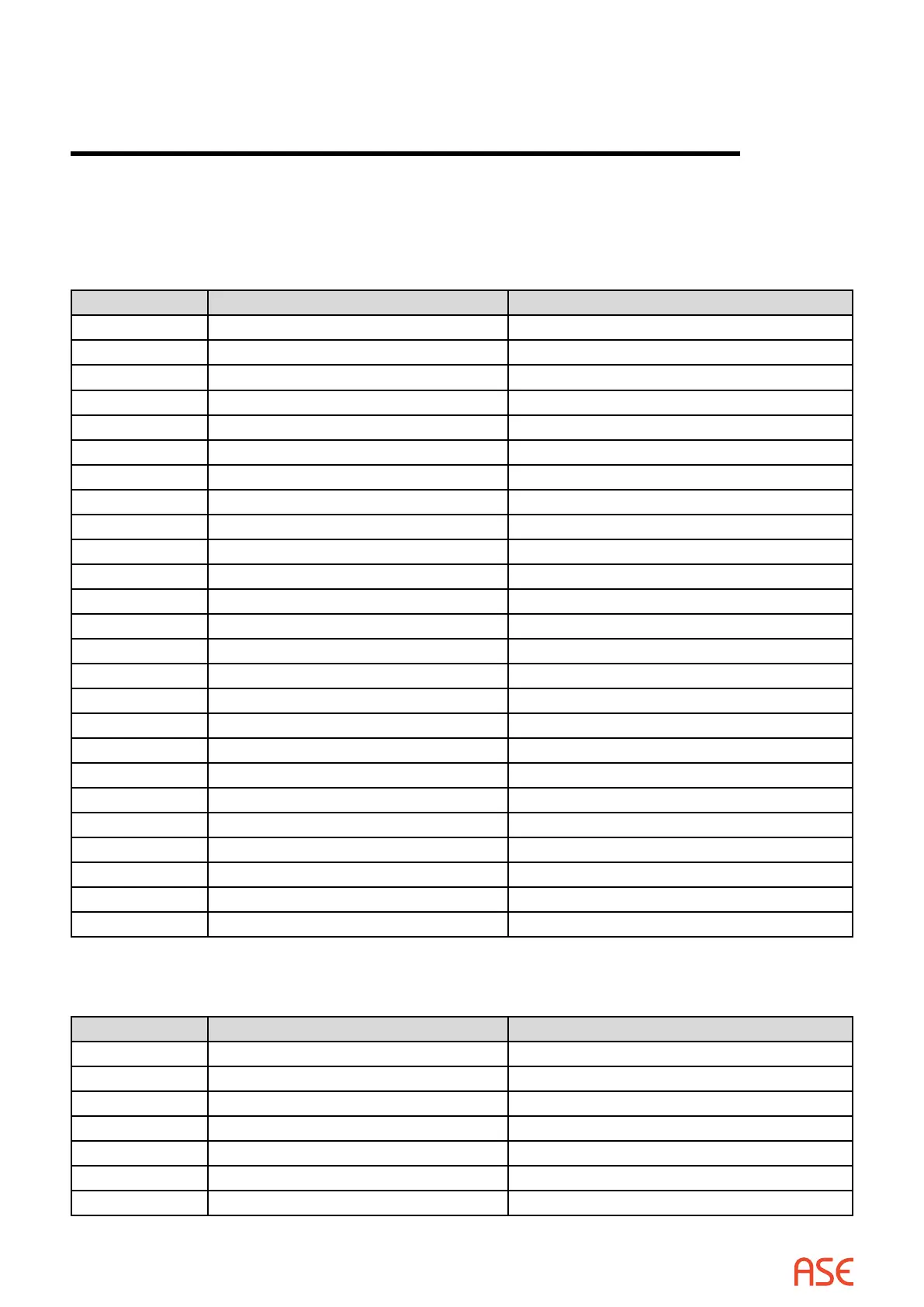
17.1. DB-25 Connector PIN-OUT
Pin Signal Name Signal Description
1 ---- Protective Ground
2 TXD Transmitted Data
3 RXD Request To Send
4 RTS Request To Send
5 CTS Clear To Send
6 DSR Data Set Ready
7 GND Signal Ground/Common
8 CD Carrier Detect
9 --- +Voltage
10 --- -Voltage
11 --- ----
12 SCF 2nd Line Detector
13 SCB 2nd Clear To Send
14 SBA 2nd Transmitted Data
15 DB DCE Element Timing
16 SBB 2nd Received Data
17 DD Received Element Timing
18 ----- Unassigned
19 SCA 2nd Request To Send
20 DTR Data Terminal Ready
21 CG Signal Quality Detector
22 RI Ring Detector
23 CH/CI Data Signal Rate Detector
24 DA DTE Element Timing
25 ---- Unassigned
17.2. DB-9 Connector PIN-OUT
Pin Signal Name Signal Description
1 CD Carrier Detect
2 RXD Receive Data
3 TXD Transmit Data
4 DTR Data Terminal Ready
5 GND Signal Ground/Common
6 DSR Data Set Ready
7 RTS Request To Send
17
 Loading...