ASE2000 V2 Communication Test Set User Manual 155
26.1.5. DNP3 – Point Value Simulation
When acting as a RTU Simulator, the ASE2000 responds to all master requests including those
for analog, binary, or counter object values. This section provides instructions to dene values
and point modeling parameters for each input object type.
►
The procedures below are used only for Exchange Mode RTU Simulator. For Task
mode, please refer to the Task Mode RTU Simulation section
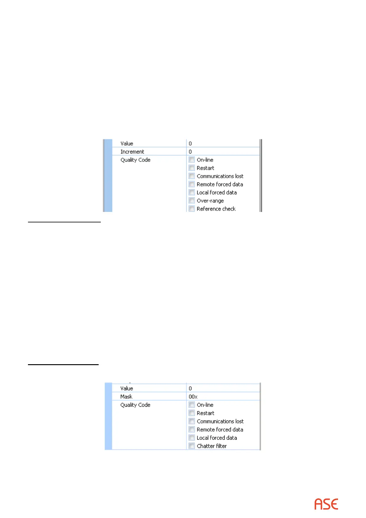
Point values and modeling parameters are entered from the Object’s properties menu as
described in the prior subsection. The appropriate elds from that menu are Value, Increment
(replaced by Mask for Binary Points), and Quality Code.
Analog Parameters
The menu above shows value and modeling parameters for analog objects.
Value species the value to be sent in the next response. This is used for all analogs dened
by the underlying object group denition. For example, if the denition species analog object
indices 0 to 7, the same value is used for all 8 objects.
Increment species an amount to add to the value eld after each response. Values are
incremented to a maximum and then decremented by the same amount to a minimum. The
cycle is repeated. Maximum and minimum values are set by the ASE2000; the defaults for DNP3
protocol are +32767 and -32768. They can be viewed and changed from the Properties dialog
and Point tab.
Quality codes present all Analog object DNP3 quality codes. The message will be sent with all
quality codes checked.
Binary Parameters
The following menu appears for binary input objects:
Value is an 8-bit octet containing states for each set of 8 points. The low bit denes the state of
the rst point in each set of 8. The high bit denes the state for last point in each set of 8. Note
that this value can be entered in hex by specifying an ‘x’ sux. For example, 81 is decimal and
81x is hex.
 Loading...