ASE2000 V2 Communication Test Set User Manual 69
For example, assume a DNP3 device with:
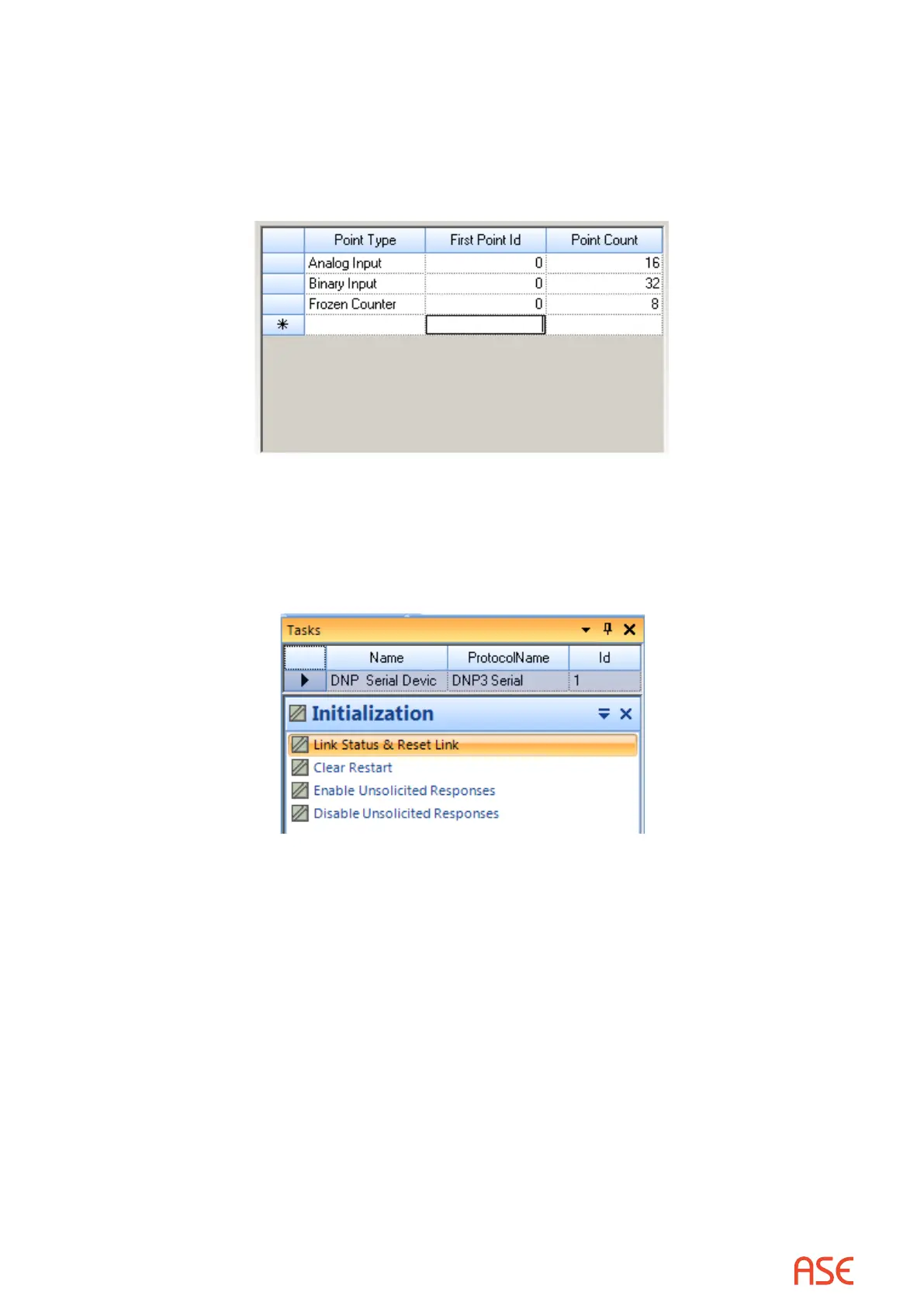
• 16 analog inputs starting at address 0,
• 32 binary inputs starting at 0, and
• 8 frozen counters, also starting at 0
After all information is entered, the menu will appear as shown below.
Complete the denition process by selecting the Finish button.
The Task Menu now shows the newly dened device. Since the device was selected as the
active device, the Task List now shows tasks from the rst task group for the active device’s
protocol (DNP3).
Make sure the correct communication mode, Master Simulation, RTU Simulation, or Line Monitor,
is selected. Following sections describe continuing procedures for each mode.
10.3. Task Mode Operation, Master Simulation Mode
10.3.1. Task Selection and Navigation
Tasks are presented in groupings applicable to each protocol. For example, DNP3 protocol has
task groupings for:
• Initialization
• Acquisition of Static Data
• Acquisition of Event Data
• Counter operations
• Time related operations
• Control outputs
• File operations
• Secure Authentication
 Loading...