ASE2000 V2 Communication Test Set User Manual 97
8 CTS Clear To Send
9 RI Ring Indicator
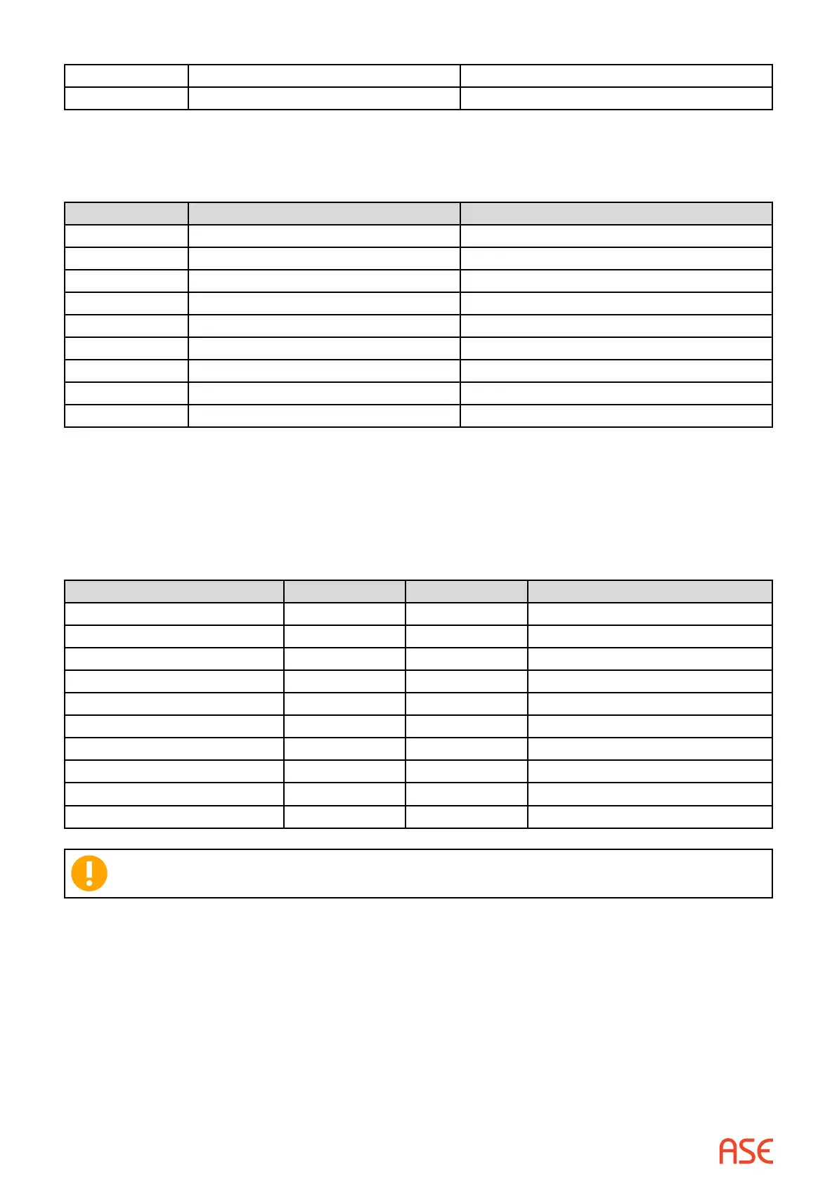
17.3. DB-9 to DB-25 Adaptor
The following table illustrates the pin-out of a “standard” DB-9 to DB-25 adaptor.
DB-9 DB-25 Signal Description
1 8 DCD – Data Carrier Detect
2 3 RXD – Receive Data
3 2 TXD – Transmit Data
4 20 DTR – Data Terminal Ready
5 7 Com – Common
6 6 DSR – Data Set Ready
7 4 RTS – Request To Send
8 5 CTS – Clear To Send
9 22 RI – Ring Indicator
This type adaptor should be used whenever it is necessary to convert between a DB-25 and
DB-9 connector.
17.4. DB-25 Null Modem Adaptor (Standard)
The following table illustrates the pin-out of a “standard” DB25 to DB-25 Null Modem Adaptor.
Signal Description DB-25M DB-25F Signal Description
Protective Ground 1 1 Protective Ground
TXD – Transmit Data 2 3 RXD – Receive Data
RXD – Receive Data 3 2 TXD – Transmit Data
RTS – Request To Send** 4 8 DCD – Carrier Detect
CTS – Clear To Send** 5 8 DCD – Carrier Detect
DSR – Data Set Ready 6 20 DTR – Data Terminal Ready
COM – Common (Sig. Gnd) 7 7 COM – Common (Sig. Gnd)
DCD – Carrier Detect 8 4 RTS – Request To Send**
DCD – Carrier Detect 8 5 CTS – Clear To Send**
DTR – Data Terminal Ready 20 6 DSR – Data Set Ready
**Note: Pins 4 and 5 (RTS, CTS) on both the DB-25 Male and DB-25 Female side are
tied together and connected to pin 8 (DCD) of the other side.
 Loading...