ASE2000 V2 Communication Test Set User Manual 174
In RTU Simulation mode, after receiving a request for Class 0, 1, 2, or 3 data, the ASE2000
generates a response message from all enabled and properly congured exchanges in the
requested class or classes.
26.7. DNP3 – Task Mode
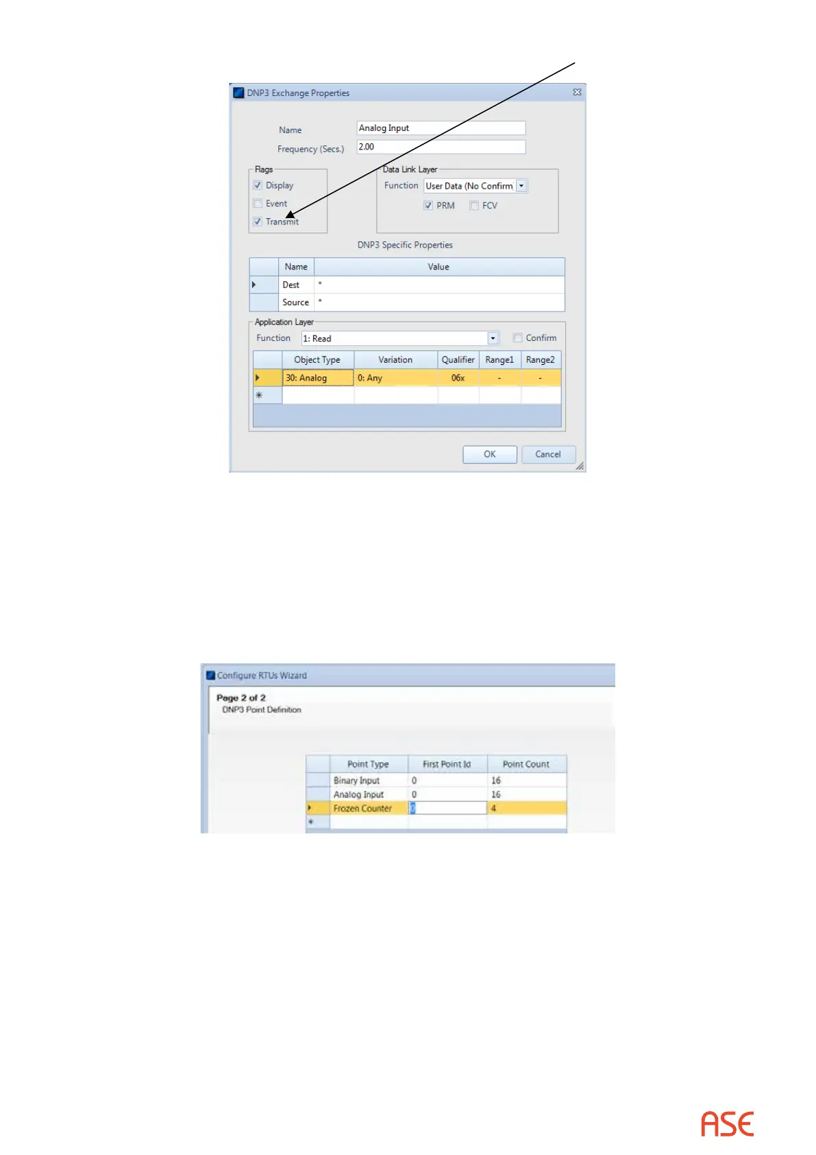
Virtually all Task Mode setup starts by rst conguring points/objects in the RTU data base. For
example:
The conguration shown above creates 16 Binary Inputs, 16 Analog Inputs, and 4 Frozen
Counters.
26.7.1. DNP3 – Task Mode Line Monitor
No additional setup is required. If cabling is correct, Line Monitoring can be started by selecting
the Start button.
While it is best to accurately enter the RTU/point data base as described, completeness is not
required for Line Monitor operations. An undened input point is automatically added to the data
base when detected.
 Loading...