ASE2000 V2 Communication Test Set User Manual 147
25.2. Conitel – Task Mode
For all protocols, Task Mode setup starts by rst conguring an RTU and RTU point conguration
in the device data base or selection of an existing RTU denition. See the non-protocol specic
section “Task Mode Device Selection and Conguration”. The steps described below for
activating Line Monitor, Master Simulation, and RTU Simulation activities assume the correct
RTU conguration has been selected.
25.2.1. Conitel – Task Mode Line Monitor
No additional setup is required. If cabling is correct, Line Monitoring can be started by selecting
the Line Monitor icon
on the bottom of the test set screen and then selecting the
Start butto n
.
While it is best to accurately enter the RTU/point data base as described, it is not required for
Line Monitor operations. An undened input point is automatically added to the data base when
detected.
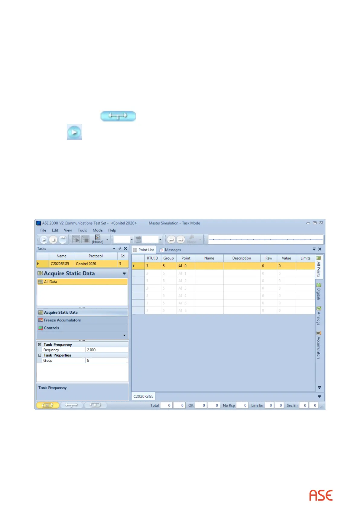
25.2.2. Conitel – Task Mode Master Simulation
Master Simulation operation works by selecting a Task Group and then a Task Activity within that
group.
For Conitel, the Task Groups are Acquire Static Data, Freeze Accumulators, and Controls.
With the desired Task Activity selected, execute the function once using the Send Once icon or
continuously by selecting the Start Button.
 Loading...