ASE2000 V2 Communication Test Set User Manual 45
ICON Name In Exchange Mode In Task Mode
Stop Stops communication Stops communication
Resume N/A Resumes communication
7.3.2. Time Line
The Time Line contains a real-time presentation of communication trac showing data and
carrier signals in both directions (master requests and device responses)
7.3.3. Capture File Control
A capture le records communication line trac over a period of time. A capture le contains
message information obtained while enabled.
ICON Name Description
Start Starts le capture
Stop Stops le capture (should use an enabled icon)
File Selection Used to specify and enable a specic capture le. The ICON
contains the name of the currently active (most recently
selected) le, Capture1 in this example
Information recorded to the active capture le can be viewed by selecting File and View Capture
or clicking the le selection icon
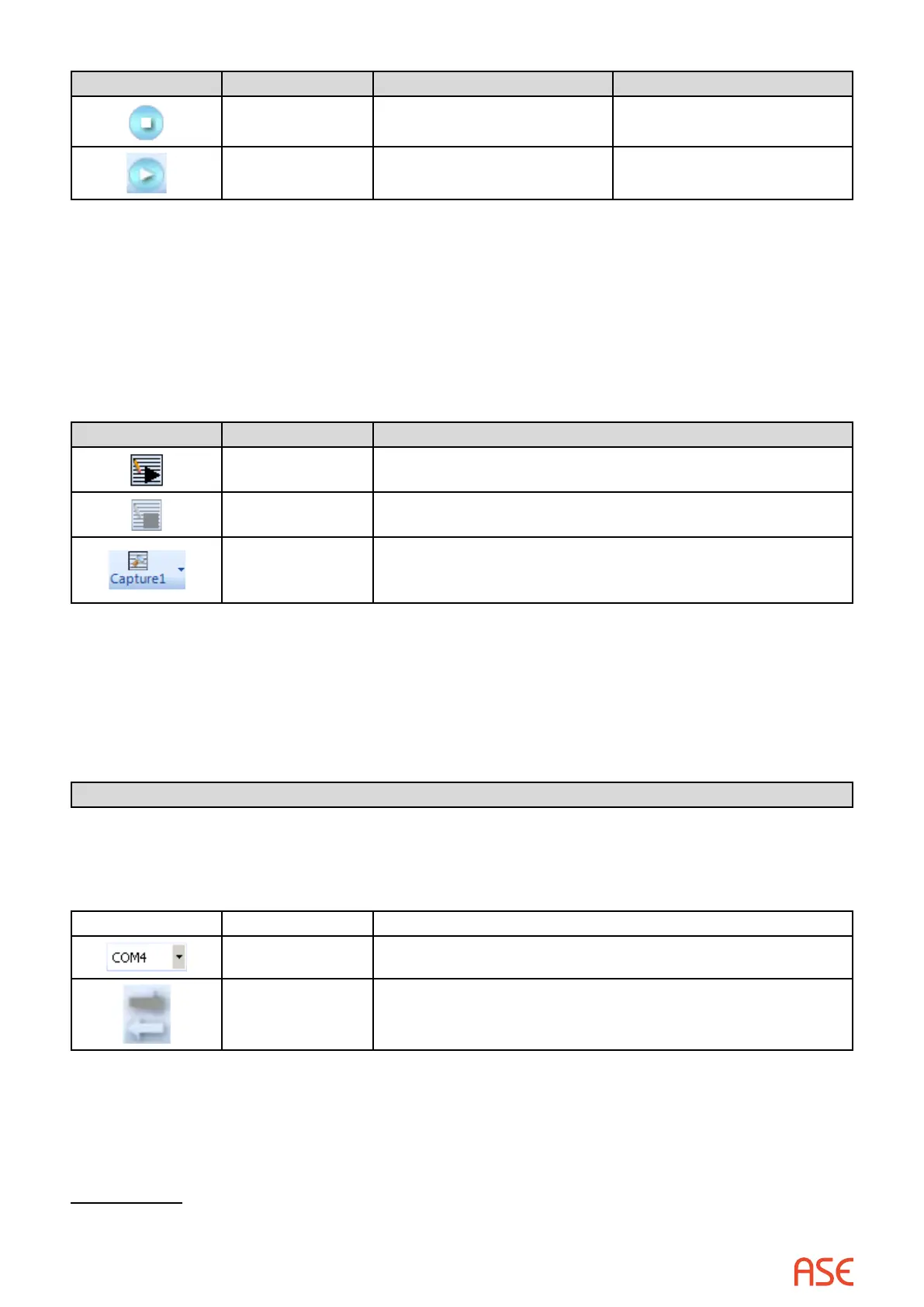
7.3.4. Communication Port Selection
This section can show one of two sets of ICONs. The rst is shown when a serial protocol is
selected. The second is show for network protocols.
Serial Protocol Ports, Master and RTU Simulation
The serial protocol set allows entry of two COM ports. One COM port, identied as “To RTU”,
communicates to the RTU (IED or PLC). In Master Simulation mode, it is the only port used. The other
COM port, identied as “To Master”, communicates to the master. In RTU Simulation mode, it is the only
port used. Both ports are used in Line Monitoring mode. Messages from the RTU should be received on
the “To RTU” port and messages from the master on the “To Master” port
1
.
ICON Name Description
COM ports Pull-down lists allow for COM port selection
Direction Switches the “To RTU” and “To Master” ports
1 When monitoring communication for a protocol with direction information in the message, such as DNP3, the ASE2000
interprets messages correctly regardless of which port is “to RTU” and which is “To Master”
 Loading...