ASE2000 V2 Communication Test Set User Manual 98
17.5. DB-9 Null Modem Adaptor (Standard)
The following table illustrates the pin-out of a “standard” DB9 to DB-9 Null Modem Adaptor.
Signal Description DB-9M DB-9F Signal Description
DCD – Data Carrier Detect 1 7 RTS – Request To Send**
DCD – Data Carrier Detect 1 8 CTS – Clear To Send**
RXD – Receive Data 2 3 TXD – Transmit Data
TXD – Transmit Data 3 2 RXD – Receive Data
DTR – Data Terminal Ready 4 6 DSR – Data Set Ready
COM – Common (Sig. Gnd) 5 5 COM – Common (Sig. Gnd)
DSR – Data Set Ready 6 4 DTR – Data Terminal Ready
RTS – Request To Send** 7 1 DCD – Data Carrier Detect
CTS – Clear To Send** 8 1 DCD – Data Carrier Detect
**Note: Pins 7 and 8 (RTS, CTS) on both the DB-9 Male and DB-9 Female side are tied
together and connected to pin 1 (DCD) of the other side.
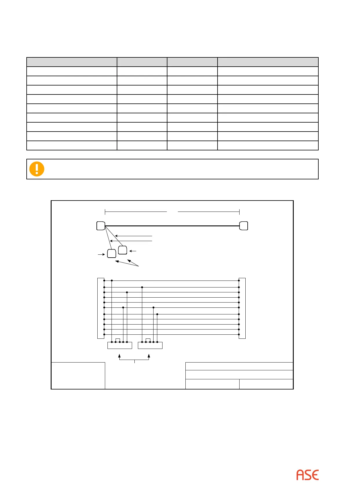
17.6. ASE RS-232 Monitor Adaptor Cable
DB25 Female
DB25 Female DB25 Male
8 ft.
2
3
4
5
6
7
8
15
17
20
24
2
3
4
5
6
7
8
15
17
20
24
Transmit Data
Receive Data
Request to Send
Clear to Send
Data Set Ready
Signal Ground
Carrier Detect
Transmit Clock
Receive Clock
Unused
Data Terminal
Ready
3 4 5 7 8 3 4 5 7 8
NOTE: Pins 4 and 5 are
jumpered within the
connector
1 ft. (cable length)
APPLIED SYSTEMS ENGINEERING, INC.
TGEN-110 Monitor Adaptor Cable
Revision 2 4/5/2001
NOTES:
1. 24 Guage Wire
2. Unshielded Cable
Please label
connector "DTE"
Please label
connector "DCE"
(DTE) (DCE)
 Loading...