ASE2000 V2 Communication Test Set User Manual 202
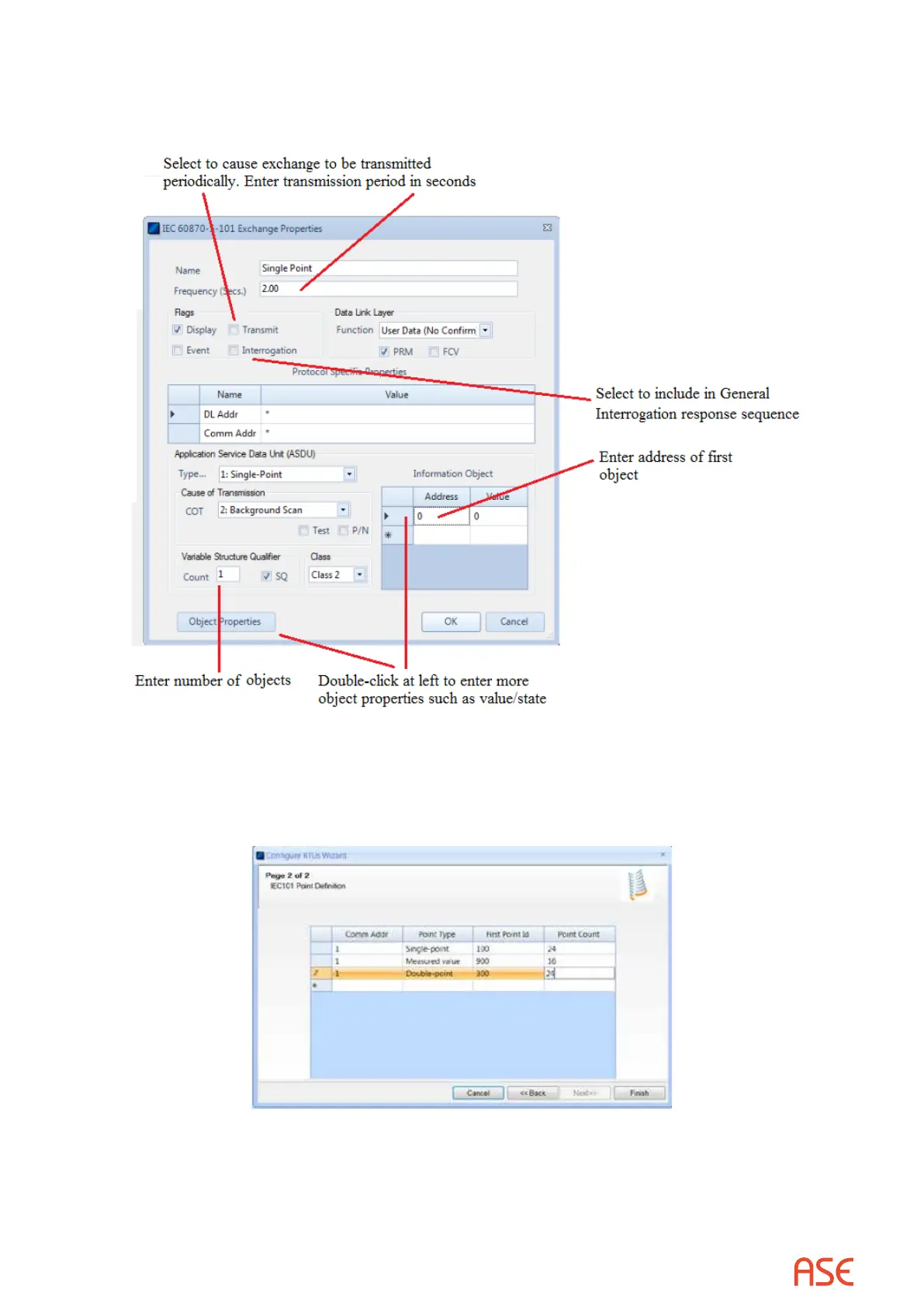
be sent to the master, edit transmission information from the Exchange Proprieties menu. The
example presented below is for Single Points. While other properties than those shown can be
entered, a basic RTU simulation conguration requires entry only of those shown.
28.9. IEC 60870-5 – Task Mode
Virtually all Task Mode setup starts by rst conguring points/objects in the RTU data base. For
example:
The conguration shown above creates 24 Single Points, 16 Measured Values, and 24 Double
Points with consecutive Information Object address starting at the address contained under the
First Point ID column.
 Loading...