ASE2000 V2 Communication Test Set User Manual 203
28.9.1. IEC 60870-5 – Task Mode Line Monitor
No additional setup is required. If cabling is correct and Interoperability settings entered, Line
Monitoring can be started by selecting the Start button.
While it is best to accurately enter the RTU/point data base as described, completeness is not
required for Line Monitor operations. An undened input point is automatically added to the data
base when detected.
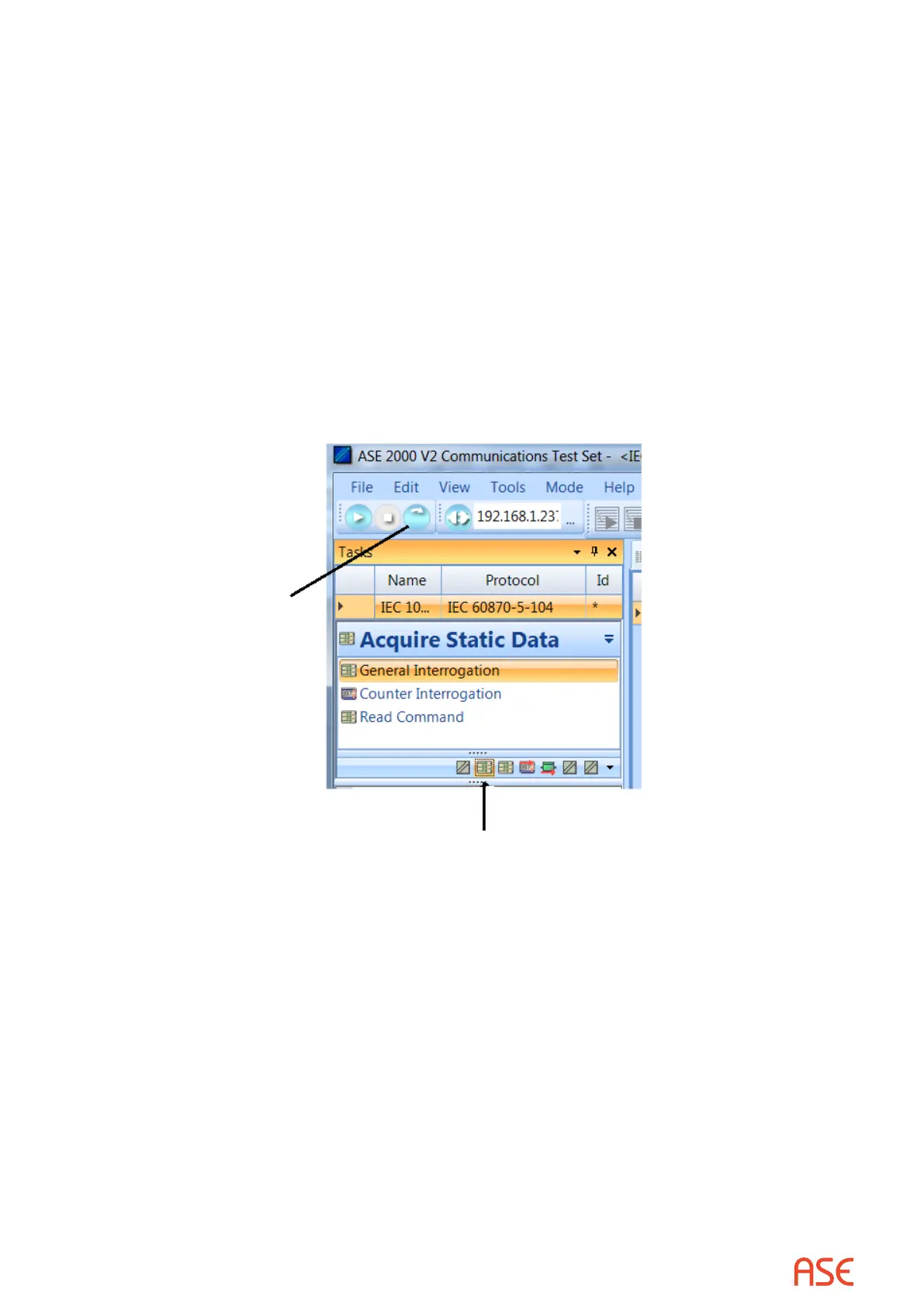
28.9.2. IEC 60870-5-101 Task Mode Master Simulation
Master Simulation operation works by selecting a task group in the middle of the Tasks View
and an individual task within that group. The best way to obtain process (input) data from an IEC
60870-5-101 Controlled Device (RTU) is to:
• Select and send once the General Interrogation task from within the Acquire Static Data
grouping
• Select and play continuously the Class Scan task from within the Acquire Exception Data
grouping
 Loading...