ASE2000 V2 Communication Test Set User Manual 58
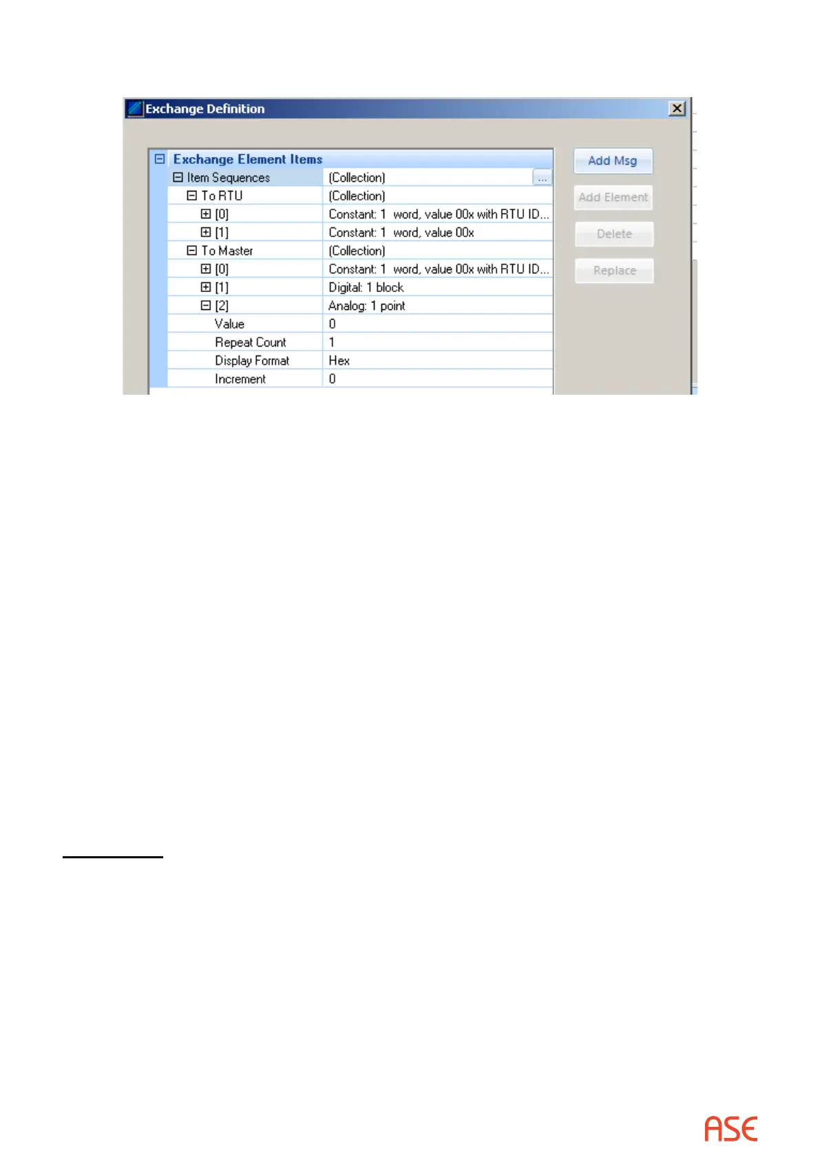
Restore the original Edit Exchange Denition menu. This will now appear as:
A new Analog element has been created
• Set the Repeat Count to 7, for 7 analog points, or, alternatively, to 0. A count of 0 always
means that the rest of the message is a sequence of values of the current type. So, 7 means
7 analogs, and 0 means the rest of the message are analogs
• Select OK to end the editing process
The edited denition will cause the input message to be parsed accordingly.
This type of editing is useful for protocols where:
• The type of point returned in a scan request is known by the user, but is neither known in
advance by the ASE2000 nor can be deduced from the input message
• The number of points in the data response is known by the user, but is neither known in
advance by the ASE2000 nor can be deduced from the input message
In all other cases, the ASE2000 should be able to analyze the input message and display input
data point appropriately without editing the Exchange Denition
►
Note that exchanges are not used in Task Mode so exchange editing is not required.
The ASE2000 automatically makes similar adjustment based on user entered Point
Information
Other Uses
There is one more important aspect of the Exchange Denition menu applicable to RTU
Simulation. As a RTU, the ASE2000 can respond with a value for each input point and can
modify this value in each scan response.
Refer to the data entry menus for analog and digital input points.
• The Value eld denes the value to be included in the next scan response. For analog and
pulse accumulator points, this is a raw numeric value. For digital input points, value denes
a block of points. The rightmost bit is the state of the rst point. Other point states occupy
successive bits to the left
• For analog points, the Increment eld species a number to add to the Value eld after each
response. The new Value will be used in the next response. Once a maximum analog value
has been reached (depending on the protocol) the sign of the Increment eld will change,
 Loading...