ASE2000 V2 Communication Test Set User Manual 74
Single Point Control
Before activating an analog control, the user must enter:
• Control point index: The default, ‘*’, indicates that no index has been entered. The ASE2000
will reject an attempt to activate a control action until a valid index is entered
• Value: Analog output value. Unless modied, the default value, 0, is used
Once correct values are entered for the above properties, the control task can be activated. The
setup discussed above will result in control of a single point with a single value. If the Start icon
is selected, the same control (index and value) will be sent repetitively.
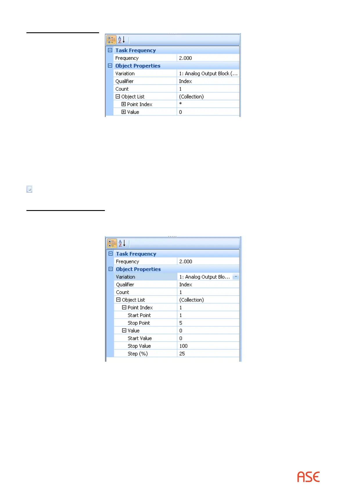
Multiple Point Control
Properties to control multiple points with multiple values are accessible by selecting the [+]
targets at the left of the Point Index and Value elds.
The Point Index eld has Start Point and Stop Point subelds, the same as described for
Digital Controls. The Value eld has Start, Stop, and Step Percentage subelds. The subelds
dene ranges for analog control commands.
For example, the settings shown above congure the ASE2000 to issue commands to:
• Analog output indices 1 through 5, with
• Values ranging from 0 to 100 in 25% increments
 Loading...