ASE2000 V2 Communication Test Set User Manual 91
In Monitor Mode, the ASE2000 test set forces the network interface to operate in what is called
“promiscuous” mode. This allows the test set to read network messages that are not addressed
to the device the test set is running on. In order for this to work, it is necessary for the test set
PC and either the SCADA Master or the remote device to be on a common network segment.
This is most commonly accomplished by plugging the devices into a common hub; not a router
or switch. It is necessary to use a hub in this case so the messages between the devices being
monitored will be present on the LAN segment the test set is connected to. A router or switch
will only pass messages to a port if the addressed device is known by the switch or router to be
connected to that port. So, if you connect the test set directly to a port on a router or switch for
monitoring purposes it won’t work since the router/switch will not pass the data to that port. As
described above, a router or switch can be used for Master or RTU mode but not Monitor mode.
Since a hub passes all data to all connected ports, data for the devices being monitored will be
available to the test set only if the test set and at least one of the devices being monitored is
connected to the hub. It is possible, and most likely necessary, to use routers and switches in
other parts of the network but a hub must be used for the monitored devices. See connection
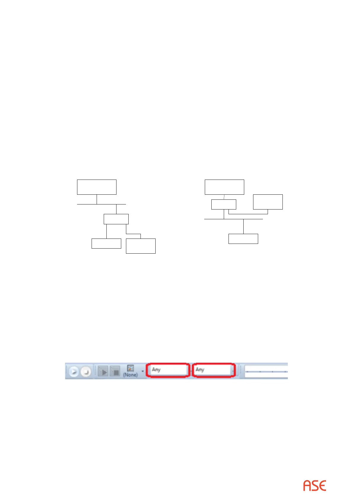
examples below.
SCADA
Master
RTU
Hub
ASE2000
Test Set
Monitor Mode
SCADA
Master
RTU
Hub
ASE2000
Test Set
Monitor Mode Example 1 Monitor Mode Example 2
As with serial communication, it is possible to lter the data processed and displayed by ASE2000
test set using network protocols. With serial communications, the ltering is accomplished by
setting the device address on the Exchange List view. With network protocols, ltering can be
set at the IP addresses level and the device address level.
To set an address lter at the IP address level, enter the host name or IP address of the device to
be monitored. The default value “Any” will display messages between all devices on the network
segment using the designated protocol. Select the IPv6 option on the LAN/WAN Properties page
when entering Host addresses using the broader IPv6 address space.
 Loading...