Chapter 1 – Installation of the instrument
UM-22100H-U User manual ATEQ D520 Page 20/122
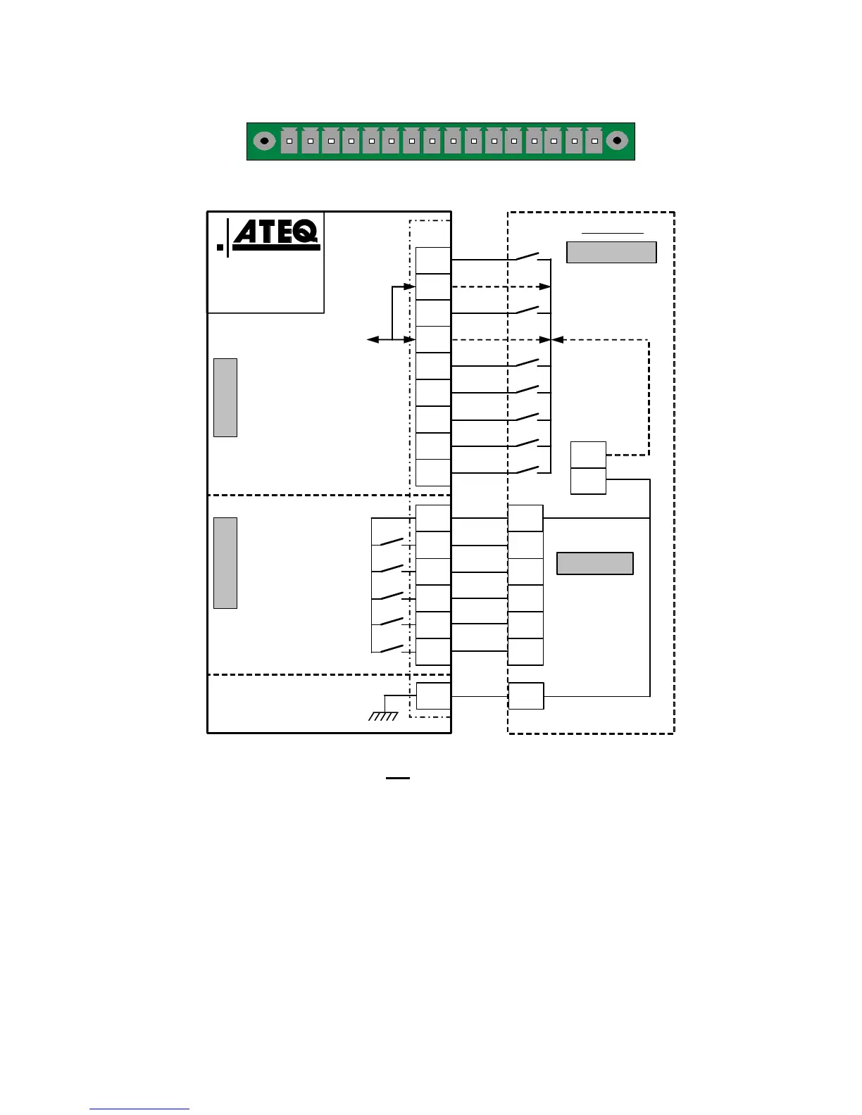
2.2.1. 6) J3 connector (Inputs/Outputs AON) diagram
1 2 3 4 5 6 7 8 9 10111213141516
a) PLC in NPN mode connection
I
1
(Reset)
Customer
Input boards
16/32 programs
I
2
(Start)
I
3
(Pr 1 + 1)
I
4
(Pr 2 + 1)
Good part
Common
Test fail part
Reference fail part
Alarm
End of cycle
24 V DC
24 V DC
ATEQ or customer
I
6
(Pr 8 + 1)
I
5
(Pr 4 + 1)
I
7
(Programmable input)
16
15
14
13
12
11
10
9
8
7
6
5
4
3
2
1
NPN MODE
Ground
+ 24 V DC
J3
INPUTS OUTPUTS
OUTPUTS
+
-
INPUTS
Customer
0 V
(0,3 A max)
Note: The 24V power supply must be provided by the internal power supply of the
ATEQ instrument (0,3A maximum) OR
through an external power supply provided by
the customer.
In the case of customer external supply, the ATEQ instrument can be supply by the 2
and 4 pins on the J3 connector too.