DL205 User Manual, 4th Edition, Rev. B
Chapter 5: Intelligent Box (IBox) Instructions
1
2
3
4
5
6
7
8
9
10
11
12
13
14
A
B
C
D
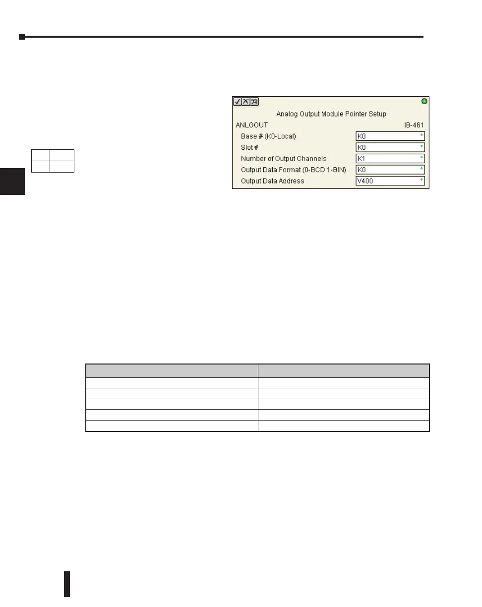
Analog Output Module Pointer Setup (ANLGOUT) (IB-461)
Analog Output Module Pointer Setup generates the logic to configure the pointer method for
one analog output module on the first PLC scan following a Program to Run transition.
This IBox determines the data format
and Pointer addresses based on the
CPU type, the Base#, and the Slot#.
The Output Data Address is the
starting location in user V-memory
where the analog output data values
will be placed by ladder code or
external device, one location for each
output channel enabled.
Since this logic only executes on the
first scan, this IBox cannot have any
input logic.
ANLGOUT Parameters
• Base # (K0-Local): specifies which base the analog module is in
• Slot #: specifies which PLC slot is occupied by the analog module
• Number of Output Channels: specifies the number of analog output channels that will be used
• Output Data Format (0-BCD 1-BIN): specifies the format of the analog output data (BCD or
Binary)
• Output Data Address: specifies the starting V-memory location that will be used to source the
analog output data
DS5 Used
HPP
N/A
Parameter DL205 Range
Base # (K0-Local) . . . . . . . . . . . . . . . . . . . . . . . K K0-3
Slot # . . . . . . . . . . . . . . . . . . . . . . . . . . . . . . . . . K K0-7
Number of Output Channels . . . . . . . . . . . . . . . K K1-8
Output Data Format (0-BCD 1-BIN). . . . . . . . . . K BCD: K0; Binary: K1
Output Data Address . . . . . . . . . . . . . . . . . . . . . V See DL205 V-memory map - Data Words
5–236

 Loading...

